A related question is a question created from another question. When the related question is created, it will be automatically linked to the original question.
If you have a related question, please click the "Ask a related question" button in the top right corner. The newly created question will be automatically linked to this question.
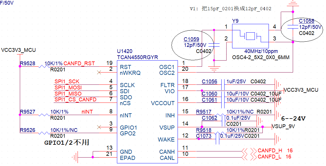
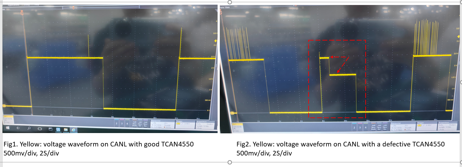
now customer find a abnormal voltage waveform with a failure TCAN4550, comparing with a good TCAN4550. is it possible for any error register configure to cause this? the schematic (same as that in above ) and high size waveforms are attached.
Does the failed TCAN4550 device have any problems communicating? Or is the only failure result noticed here the different voltage level?
It is common for the common-mode of a CAN line to fall in between the 2.5V nominal level and GND when the CAN bus is idle for some time. This is caused by one or more transceivers moving into a low-power Sleep state while other devices remain active. The active transceivers bias the bus to 2.5V while the Sleep mode devices weakly bias it to ground. Because there is no communication in this state (the bus is idle) there is no impact to any active signal or emissions profiles. Once the bus becomes active again (any CAN communication), the Sleep mode devices will wake up and help bias the bus to 2.5V. This appears to be what happens in the second half of Figure 2.
Let me know if I misunderstand anything about the report here and if there are any larger issues apart from the expected intermediate bus voltage observed on CANL.
Does the failed TCAN4550 device have any problems communicating?
------Yes, the failed TCAN4550 device cause communication problem.
There is no MCUin my hand to control TCAN4550 EVM .Is any way to check if the defective TCAN4550 is damaged via our TCAN4550 EVM without using software (or SPI ) control( only by hardware control)?
How are you evaluating the TCAN4550? Is there an MCU involved here? Or is this after the failure you do not have an MCU to test the failed device?
Does the failed device stop other nodes from communicating on the bus? Is it capable of receiving CAN communication? Does any condition allow the failed unit to communicate again such as a POR?
Does replacing the TCAN4550 unit on the customer board resolve the communication issues? If the faulty unit is placed on a working customer board, does the communication failure follow the transceiver? If so, it sounds like we should treat this as a damaged unit case. If so, do you know if they have conducted any EMI testing such as ESD strikes? If so, please share the test name and levels used. Are there any ESD diodes placed on the CAN bus?