This thread has been locked.

If you have a related question, please click the "Ask a related question" button in the top right corner. The newly created question will be automatically linked to this question.

SN65176B: Communication error on receiving from RS485

Part Number: SN65176B
Other Parts Discussed in Thread: THVD1520

Dear all,

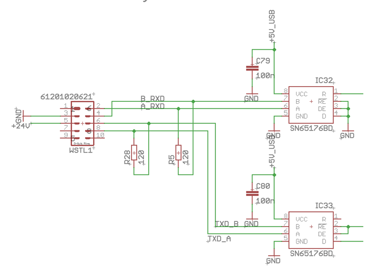
I'm observing a communication error when receiving from a RS485 line with transceiver SN65176. This issue occurs (so far) on a single board out of 200.

Just before the data transfer starts, the SN65176 part sends the R pin (RX output) low. The receiving end sees a "break" or 0x00 byte which leads to data corruption.

This scope shot shows the relevant signals when the issue occurs:

Scope Shot

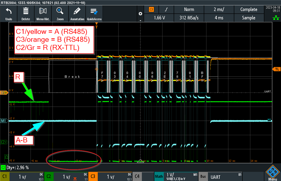
The RS485 signals A and B are on channel 1 and 3 (yellow and orange lines, respectively).
The R signal is on channel 2 (green line) and being decoded (white lines and text).
The differential Signal V_A-B is on channel Math1 (cyan line).

The data is correct, however, the leading "Break" is adding a bogus data byte which leads to a communication error.

I already replaced the transceiver. This did not help.

Why is R going low although V_A-B does not change. I don't understand this.

Please advise.

Thanks.

Daniel

  • For your information, this is the schematic for the RS485 connection:

     Schematic

  • The differential input voltage is zero. This state is not allowed (see the second line in table 7-2), and the R output might be either high or low, randomly. You were lucky that the input's hysteresis kept it in the high state.

    To force the bus to have a defined state even when no transmitter is active, add fail-safe pull-up/-down resistors on the A/B lines. Alternatively, use transceivers with fail-safe inputs (e.g., THVD1520), which have a defined state when their inputs are shorted.

  • Hi Clemens,

    Thank you for the immediate response.  The TI support is one of the reasons I'm designing with TI parts.Thumbsup

    I added a 680 Ohm pull-up resistor to A and a 680 Ohm pull-down resistor to B. 

    Now the "forbidden state" does not appear any longer, see this scope shot:

    Scope Shot

    Now, in the idle state, the difference between the signal on line A and line B is about 400 mV. That exceeds the transceivers threshold of 200 mV and thus provides a defined signal state. 

    Seems to work. Great.

    Best regards,

    Daniel

  • Hi Daniel,

    I am glad Clemens was able to help you with this issue!

    For future reference we do have an design guide on how to set these resistors up located here. While I will say 680 Ohms is pretty common for these biasing resistors - there could be situations where the resistance is slightly different. 

    If you need any other support please let me know!

    Best,

    Parker Dodson