This thread has been locked.

If you have a related question, please click the "Ask a related question" button in the top right corner. The newly created question will be automatically linked to this question.

DS90UB954-Q1: Communication issue - Margin Analysis show low margin

Part Number: DS90UB954-Q1
Other Parts Discussed in Thread: , DS90UB953-Q1, DS90UB953-Q1EVM, ALP

Hi,

I am working on a project where we are using a deser-ser couple to develop a communication between our board and a remote CSI cmos sensor.

We developed our custom board with the deser (DS90UB954-Q1), following design rules as much as possible.

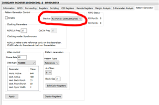
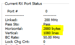
Now, we checked the communication integrity by using the margin analysis, integrated in the Analog LaunchPAD software and we got the following result, which is quite poor:

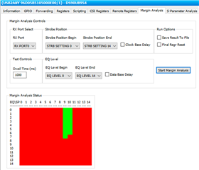
To get the result we used a DS90UB954-Q1EVM evaluation board, we connected the external I2C port to the I2C input of our deser (soldered on our custom board), we checked that our deser had the correct I2C address (different from the address of the deserializer on the EVM board) and we launched the test.

We tried different cable length, but unfortunately the result is similar. Moreover, also using a different port (port 0 or port 1) to connect the coaxial cable the result is the same.

What do you suggest to improve the signal integrity?

Is there another test i can do to better understand what is the problem?

If I send you my PCB design, can you check if there is some macroscopic error?

Thank you in advance.

Best regards,

Alessandro

  • Hi Alessandro,

    What serializer are you using with the 954? Is the system still operating correctly despite the poor margin, or are you having some issues here as well?

    Are you getting stable lock on the 954? You can read register 0x4d repeatedly to see the current lock status and if the lock status has changed recently. Make sure you select the correct RX port before reading 0x4d.

    What types of cables and cable lengths have you tried? Did you get similar margin results when trying different cable lengths?

    I can review your schematic and PCB layout, but I'd like to better understand what issues you're dealing with first.

    Best,

    Lucas

  • Hi Lucas,
    Thank you very much for your answer.
    I am using the DS90UB953-Q1 serializer. To perform the Margin Analysis I am using the DS90UB953-Q1EVM evaluation board, connected to our board by means of a Fakra-female - SMA-male coaxial cable.
    I tried different cables I have in my lab and the resul is allways the same. In particular, I tried with a 12cm cable and a 4m cable, getting similar results.
    In addition, I tried the margin analysis between 954EVM and 953EVM and the result is very good, so I am quite sure that the problem is my custom 954 board.

    I now try to read continuously register 0x4D on port 0 and I come back to you with the result.


    Best regards,
    Alessandro

  • Hi Alessandro,

    Your analysis makes sense to me and I agree that layout issues seem to be a likely cause for the poor margin. Can you send your schematic and PCB layout for review? And can you also share the register 0x4D values once you have tested?

    Best,

    Lucas

  • Hi Lucas,
    I sent you a private message with our project attached, so you can start looking at it.
    I will send you my tests on register 0x4D as soon as possible.
    Best regards,
    Alessandro

  • Hi Lucas,
    I made the test that you suggested: I read continuously the register 0x4D for about 10 minutes, once every 50ms and I got allways the same result = 0x03, meaning that lock and pass are true and that lock status never changed during the experiment. 

    I tried with both a short cable (12cm) and a long one (5m) and the result was allways the same.

    What do you think about it? The system is stable even if the margin is low? Is there any other test I can do?
    I saw on application note that I can do a so-called BIST test. Do you think it can be useful to better understand the situation?

    Best regards,

    Alessandro

  • Hi Alessandro,

    It's definitely promising that your link is stable despite the margin analysis results. Running BIST can definitely be helpful to test link stability. BIST operation is explained in section 7.5.12 of the 954 datasheet.

    Another test you can run is configuring patgen on the 953 and seeing if the data is transmitted to the 954 without errors. You can use the Patgen tab on ALP to set your resolution/encoding parameters on the 953, then check registers 0x4d, 0x4e, 0x55, 0x56, 0x7a, and 0x7b on the 954 for errors.

    I'll hold off on the layout review for now, to see how your system performs with BIST and patgen tests.

    Best,

    Lucas

  • Hi Lucas,
    I tried the BIST test as you suggested.
    To do it, I followed the  script in the application note snla267a (How to Design a FPD-Link III System Using DS90UB953-Q1 and DS90UB954-Q1 (Rev. A) (ti.com)) at page 34.
    You find the complete procedure in the following. In blue I highligted the instructions, including read and write of registers of 954 deserializer (DES) and 953 serializer (SER). You find also my comments explaining what has been done and the results I got from reading registers. I highlighted in red the most critical poins and in green some questions I have regarding the test.

    //serializer reset
    WriteI2C(SER, 0x01, 0x01);

    wait(0.5s)

    //deserializer reset
    WriteI2C(DES, 0x01, 0x01);

    wait(0.5s)

    //select port 0 of deserializer
    WriteI2C(DES, 0x4C, 0x01);

    //read deser I2C_Device_ID
    data = ReadI2C(DES, 0x00);
    //result: data = 0x60 (OK! it is the deser I2C address)

    //read deser DEVICE_STS
    data = ReadI2C(DES, 0x04);
    //result: data = 0xDF (OK! LOCK=1, PASS=1, REFCLK_VALID=1, CFG_INIT_DONE=1, CFG_CKSUM_STS=1)

    //read deser RX_PORT_STS1
    data = ReadI2C(DES, 0x4D);
    //result: data = 0x13 (OK! The only error flag I see is LOCK_STS_CHG=1, meaning that lock status changed after the last readout of this register, but it is possible after reset)

    //read deser RX_PORT_STS2
    data = ReadI2C(DES, 0x4E);
    //result: data = 0x0C (OK? The only error flag I see is CSI_ERROR=1, but I think it is possible since I did not initialize the CSI communication with the sensor)

    //clear serializer errors
    WriteI2C(SER, 0x49, 0x28);

    wait(1s)

    //read serializer register 0x79 (?) -> the application note snla267a at page 36 tells to read this register, but I see on serializer datasheet that it is reserved. Why?
    data = ReadI2C(SER, 0x79);
    //result: data = 0x00 (I do not know the meaning of this register, I suppose 0x00 is correct)

    //read DEVICE STS of serializer
    data = ReadI2C(SER, 0x51);
    //result: data = 0xC0 (OK! CFG_INIT_DONE=1, CFG_CKSUM_STS=1)

    //read GENERAL_STATUS of serializer
    data = ReadI2C(SER, 0x52);
    //result: data = 0x45 (OK! RX_LOCK_DETECTED=1, LINK_LOST_FLAG=0, BIST_CRC_ERR=0, HS_PLL_LOCK=1, CRC_ERR=0, LINK_DET=1)

    //read BIST_ERR_CNT serializer before starting the bist test
    data = ReadI2C(SER, 0x54);
    //result: data = 0x00 (OK! no bist error)

    //read BIST Control on deser before starting the bist test
    data = ReadI2C(DES, 0xB3);
    //result: data = 0x08 (OK! bist disabled)

    //start bist test
    WriteI2C(DES, 0xB3, 0x01);

    //read BIST Control on deser just after the bist test has started
    data = ReadI2C(DES, 0xB3);
    //result: data = 0x01 (OK! bist test has started)

    wait(0.25s)

    //read deser RX_PORT_STS1 to clear the LOCK_STS_CHG flag (after the bist starts the system can loose lock)
    data = ReadI2C(DES, 0x4D);
    //result: data = 0x13 (OK! The only error flag I see is LOCK_STS_CHG=1, meaning that lock status changed after the test has started)

    //verify that the bist test has started on ser (read resister PORT_DEBUG on deser)
    data = ReadI2C(DES, 0xD0);
    //result: data = 0x20 (OK! SER_BIST_ACT=1, meaning that bist test has started also on serializer)

    wait(5s) //wait as much as needed to perform the bist test

    //read deser RX_PORT_STS1 to verify if lock status changed during bist
    data = ReadI2C(DES, 0x4D);
    //result: data = sometimes I got 0x03 (everything fine), some other time I got 0x07 (PARITY_ERROR=1).
    //NB: I have the parity error threshold set to 1, so a single parity error is enough to trigger the error flag. In any case, I think it is an indicator that the system is not stable. Is it correct?

    //stop bist test
    WriteI2C(DES, 0xB3, 0x00);

    //read BIST Control on deser to verify if the test has been correctly stopped
    data = ReadI2C(DES, 0xB3);
    //result: data = 0x01 (OK! bist test is not running)

    wait(0.5s)

    //read deser RX_PORT_STS1 to clear the LOCK_STS_CHG flag (I observed that stopping the bist test can change the lock status. Is it normal?)
    data = ReadI2C(DES, 0x4D);
    //result: data = 0x13 (OK! The only error flag I see is LOCK_STS_CHG=1, meaning that lock status changed)

    //read deser RX_PORT_STS2
    data = ReadI2C(DES, 0x4E);
    //result: data = sometimes I got 0x0C (everything fine xcept CSI_ERROR=1), some other time I got 0x2C (FPD3_ENCODE_ERROR=1).
    //NB: I have LINK_ERROR_COUNT enabled and LINK_ERR_THRESHOLD=3 (default value), so a FPD3_ENCODE_ERROR=1 means that the link went down at least 3 times. Is it something that can happen due to the bist test being turned off?

    //verify that the bist test has stopped on ser (read resister PORT_DEBUG on deser)
    data = ReadI2C(DES, 0xD0);
    //result: data = 0x00 (OK! SER_BIST_ACT=0, meaning that bist test is not running on ser)

    //read deser I2C_Device_ID
    data = ReadI2C(DES, 0x00);
    //result: data = 0x60 (OK! it is the deser I2C address)

    //read deser DEVICE_STS
    data = ReadI2C(DES, 0x04);
    //result: data = 0xDF (OK! LOCK=1, PASS=1, REFCLK_VALID=1, CFG_INIT_DONE=1, CFG_CKSUM_STS=1)

    //read deser RX_PORT_STS1
    data = ReadI2C(DES, 0x4D);
    //result: data = sometimes I got 0x03 (everything fine), some other time I got 0x13 (LOCK_STS_CHG=1)

    //read deser RX_PORT_STS2
    data = ReadI2C(DES, 0x4E);
    //result: data = 0x0C (OK? The only error flag I see is CSI_ERROR=1, but I think it is possible since I did not initialize the CSI communication with the sensor)

    //read DEVICE STS of serializer
    data = ReadI2C(SER, 0x51);
    //result: data = 0xC0 (OK! CFG_INIT_DONE=1, CFG_CKSUM_STS=1)

    //read GENERAL_STATUS of serializer
    data = ReadI2C(SER, 0x52);
    //result: data = 0x45 (OK! RX_LOCK_DETECTED=1, LINK_LOST_FLAG=0, BIST_CRC_ERR=0, HS_PLL_LOCK=1, CRC_ERR=0, LINK_DET=1)

    //read BIST_ERR_CNT to see if I had bist errors during test
    data = ReadI2C(SER, 0x54);
    //result: data = 0x00 (OK! no bist error)

    As you can see my system does not allways pass the test (see red comments, expecially the presence of FPD3_ENCODE_ERROR after 5 seconds of test).
    I tried the tests many times and sometimes everything goes fine and the test is passed, some other time I see the problems described above.
    I imagine that these are all symtoms 
    of system instability
    What do you tink about it?

    I also performed exactly the same test on the evaluation board of deserializer connected to the evaluation board of the serializer and I never observed problems: using evaluation boards the test allways pass, so I am quite convinced that our custom board has some design issue.
    At this point, can you proceed checking our design?

    In the meantime I will arrange the patgen test as soon as possibleto have further information.
    Best regards,
    Alessandro

  • Hi Alessandro,

    //read deser RX_PORT_STS2
    data = ReadI2C(DES, 0x4E);
    //result: data = 0x0C (OK? The only error flag I see is CSI_ERROR=1, but I think it is possible since I did not initialize the CSI communication with the sensor)

    Yes that's correct.

    //read serializer register 0x79 (?) -> the application note snla267a at page 36 tells to read this register, but I see on serializer datasheet that it is reserved. Why?
    data = ReadI2C(SER, 0x79);
    //result: data = 0x00 (I do not know the meaning of this register, I suppose 0x00 is correct)

    0x79 is a reserved register for the BCC status. A value of 00 indicates no errors.

    //read deser RX_PORT_STS1 to verify if lock status changed during bist
    data = ReadI2C(DES, 0x4D);
    //result: data = sometimes I got 0x03 (everything fine), some other time I got 0x07 (PARITY_ERROR=1).
    //NB: I have the parity error threshold set to 1, so a single parity error is enough to trigger the error flag. In any case, I think it is an indicator that the system is not stable. Is it correct?

    That's correct, any parity errors indicate potential link issues.

    //read deser RX_PORT_STS1 to clear the LOCK_STS_CHG flag (I observed that stopping the bist test can change the lock status. Is it normal?)
    data = ReadI2C(DES, 0x4D);
    //result: data = 0x13 (OK! The only error flag I see is LOCK_STS_CHG=1, meaning that lock status changed)

    Yes, it is normal to see the LOCK_STS_CHG flag when BIST begins and ends.

    //read deser RX_PORT_STS2
    data = ReadI2C(DES, 0x4E);
    //result: data = sometimes I got 0x0C (everything fine xcept CSI_ERROR=1), some other time I got 0x2C (FPD3_ENCODE_ERROR=1).
    //NB: I have LINK_ERROR_COUNT enabled and LINK_ERR_THRESHOLD=3 (default value), so a FPD3_ENCODE_ERROR=1 means that the link went down at least 3 times. Is it something that can happen due to the bist test being turned off?

    It's expected that the link would go down twice when BIST begins and ends, but more than that is not expected behavior. Seeing this FPD3_ENCODE_ERROR is definitely a concern.

    //read deser RX_PORT_STS1
    data = ReadI2C(DES, 0x4D);
    //result: data = sometimes I got 0x03 (everything fine), some other time I got 0x13 (LOCK_STS_CHG=1)

    Lock status should not be changing here.

    Please allow ~1 week for schematic and layout review. Also please share the results of the patgen test once you are able to perform it as this can be very valuable in understanding your issue.

    Best,

    Lucas

  • Hi Alessandro,

    While you are getting the patgen results, I will review your schematic/layout and provide feedback on them before Thursday, June 22. 

    Regards,

    Cindy

  • Hi Cindy,
    Thank you very much for your help.

    In the meantime I am working on patgen test. Using the ALP software I tried to set patgen configurations and I started the patgen by checking the "Enable" flag.
    Nevertheless, at this point I have a couple of questions:

    - I see that I can start the patgen either on ser or on deser (I see from datasheet that both ser and deser have a PGEN_CTL register with a PGEN_ENABLE flag) . What is the difference? Must I start the pgen from ser or from deser?
    You can see below that also the patgen software permit to enable patgen either on ser or on deser by selecting a device:


    - once the patgen is enabled I imagine that video stream is flowing through the coaxial cable. How can I verify if some error occur? Which register can I read?
    Do you have a list of registers to check after the test has been enabled?

    Thank you in advance.
    Best regards,
    Alessandro

  • Hi Alessandro,

    What is the difference? Must I start the pgen from ser or from deser?

    Both the serializer and deserializer independently have the pattern generator feature. The DES can generate a pattern and send it out of the CSI-2 transmitter. This can be helpful to confirm that valid CSI-2 data can be transferred between the DES and the SOC. The SER patgen sends the data across the link to the DES, so it is helpful to confirm the stability of the FPD-Link transferring CSI-2 data between the SER and the DES. You should enable patgen on the SER in your case.

    - once the patgen is enabled I imagine that video stream is flowing through the coaxial cable. How can I verify if some error occur? Which register can I read?

    You can verify that the 954 is receiving the correct video parameters by checking registers 0x73-0x76 (line count and line length registers).

    This data is also shown in the Information tab of the 954 ALP profile while it is receiving data:

    You can monitor the following registers in the 954 to check for errors during testing: 0x4D, 0x4E, 0x55, 0x56, 0x7A, 0x7B.

    953 Register 0x52 can be monitored to check for back channel link detect and back channel CRC errors. 

    Regards,

    Cindy

  • Dear Cindy,
    I have the patgen test results.
    You find here in the following the detailed procedure I followed to perform the test. in blue you can see the commands I send through I2C to both deserializer (DES) and serializer (SER). in red you find the most critical points were the test failed, while in green you find some doubts and questions.

    //PatGen test, 640x480, RAW10, 120fps:

    //write PGEN_CFG (indirect patgen register 0x02) = 0x25 (4 color bars, 5 blocks)
    WriteI2C(SER, 0xB0, 0x02);
    WriteI2C(SER, 0xB1, 0x02);
    WriteI2C(SER, 0xB2, 0x25);

    //write PGEN_CSI_DI (indirect patgen register 0x03) = 0x2B (VC=0, DataType = RAW10)
    WriteI2C(SER, 0xB0, 0x02);
    WriteI2C(SER, 0xB1, 0x03);
    WriteI2C(SER, 0xB2, 0x2B);

    //write PGEN_LINE_SIZE (number of bytes in 1 line) = 640*10/8 = 800 = 0x0320
    WriteI2C(SER, 0xB0, 0x02);
    WriteI2C(SER, 0xB1, 0x04);
    WriteI2C(SER, 0xB2, 0x03);
    WriteI2C(SER, 0xB0, 0x02);
    WriteI2C(SER, 0xB1, 0x05);
    WriteI2C(SER, 0xB2, 0x20);

    //write PGEN_BAR_SIZE = PGEN_LINE_SIZE/4 = 200 = 0x00C8
    WriteI2C(SER, 0xB0, 0x02);
    WriteI2C(SER, 0xB1, 0x06);
    WriteI2C(SER, 0xB2, 0x00);
    WriteI2C(SER, 0xB0, 0x02);
    WriteI2C(SER, 0xB1, 0x07);
    WriteI2C(SER, 0xB2, 0xC8);

    //write PGEN_ACT_LPF (active lines per frame) = 480 = 0x01E0
    WriteI2C(SER, 0xB0, 0x02);
    WriteI2C(SER, 0xB1, 0x08);
    WriteI2C(SER, 0xB2, 0x01);
    WriteI2C(SER, 0xB0, 0x02);
    WriteI2C(SER, 0xB1, 0x09);
    WriteI2C(SER, 0xB2, 0xE0);

    //write PGEN_TOT_LPF (active lines per frame + vertical_blanking) = 525 = 0x020D
    WriteI2C(SER, 0xB0, 0x02);
    WriteI2C(SER, 0xB1, 0x0A);
    WriteI2C(SER, 0xB2, 0x00);
    WriteI2C(SER, 0xB0, 0x02);
    WriteI2C(SER, 0xB1, 0x0B);
    WriteI2C(SER, 0xB2, 0xC8);

    //write PGEN_LINME_PD = 100000000/(120*525) [10ns] = 0x0633
    WriteI2C(SER, 0xB0, 0x02);
    WriteI2C(SER, 0xB1, 0x0C);
    WriteI2C(SER, 0xB2, 0x06);
    WriteI2C(SER, 0xB0, 0x02);
    WriteI2C(SER, 0xB1, 0x0D);
    WriteI2C(SER, 0xB2, 0x33);

    //write PGEN_VBP (vertical back porch) = 33 = 0x21
    WriteI2C(SER, 0xB0, 0x02);
    WriteI2C(SER, 0xB1, 0x0E);
    WriteI2C(SER, 0xB2, 0x21);

    //write PGEN_VFP (vertical front porch) = 10 = 0x0A
    WriteI2C(SER, 0xB0, 0x02);
    WriteI2C(SER, 0xB1, 0x0F);
    WriteI2C(SER, 0xB2, 0x0A);

    //activate interrupt flags IE_LINE_LEN_CHG and IE_LINE_CNT_CHG
    WriteI2C(DES, 0xD9, 0x60);
    //question: is this operation required? I see on deser datasheet that values in registers 0x73-0x76 are frozen until read if I activated the interrupt flags. Is it correct?

    //before I start the pattern generator I check CSI errors only to clear error flags from the registers
    data = ReadI2C(DES, 0x4E);        //here I check CSI_ERROR flag
    if(CSI_ERROR != 0){
        csi_error_number = ReadI2C(DES, 0x7B);
        csi_error_status = ReadI2C(DES, 0x7A);
    }
    //result: I see some CSI errors here, but I ignore them, since the pattern generator has not been activated yet. Error flags are cleared on read

    //before I start the pattern generator I check others errors only to clear error flags from the registers
    data = ReadI2C(DES, 0x4D);
    data = ReadI2C(DES, 0x4E);
    //result: I do not see any error here. Sometimes I see LOCK_STS_CHG in reg. 0x4D

    //start pattern generator on SER (writing 0x01 in indirect register 0x01 of patgen)
    WriteI2C(SER, 0xB0, 0x02);
    WriteI2C(SER, 0xB1, 0x01);
    WriteI2C(SER, 0xB2, 0x01);

    //just after start I check error flags in RX_PORT_STS1 and RX_PORT_STS2 and I check CSI errors:
    data = ReadI2C(DES, 0x4D); //result: 0x03
    data = ReadI2C(DES, 0x4E); //result: 0x04
    data = ReadI2C(DES, 0x7B); //result 0x00
    //result: everything fine, I see no errors

    //I leave the system for 2s with patgen active and I periodically monitor LINE_COUNT, LINE_LENGTH and RX_PORT_STS
    loop for 2s {
        line_count_msb = ReadI2C(DES, 0x73);
        line_count_lsb = ReadI2C(DES, 0x74);
        line_length_msb = ReadI2C(DES, 0x75);
        line_length_lsb = ReadI2C(DES, 0x76);
        data = ReadI2C(DES, 0x4D);
        data = ReadI2C(DES, 0x4E);
        wait(20ms);
    } //end loop
    //results: i see that during the 2-seconds patgen test sometimes I read line_count and line_length = 0. Moreover, I see sometimes RX_PORT_STS1 = 0x10 or 0x01, meaning that the system is not in LOCK and PASS state!
    I also see that often at a certain point RX_PORT_STS2 becomes 0x0C, meaning that a CSI_ERROR has been detected.

    //after the 2 seconds have passed I check CSI_ERRORS
    data = ReadI2C(DES, 0x4E);    //here I check CSI_ERROR flag
    if(CSI_ERROR != 0){
        csi_error_number = ReadI2C(DES, 0x7B);
        csi_error_status = ReadI2C(DES, 0x7A);
    }
    //result: very often I see some errors (I tried many times and I always saw csi_error_number = 1, 2, 3 or 4, so few errors if I compare them with the number of frames passed in 2s at 120fps, that is 240 frames).
    In the various tests I did I saw different values of csi_error_status: sometimes I see the flag LENGTH_ERR=1, some other times I see CKSUM_ERR=1 or ECC2_ERR=1; often it is a combination of those values.

    //stop pattern generator on SER (writing 0x00 in indirect register 0x01 of patgen)
    WriteI2C(SER, 0xB0, 0x02);
    WriteI2C(SER, 0xB1, 0x01);
    WriteI2C(SER, 0xB2, 0x00);

    //I check errors just after the patgen has been turned off
    data = ReadI2C(DES, 0x4D);
    data = ReadI2C(DES, 0x4E);
    if(CSI_ERROR != 0){
        csi_error_number = ReadI2C(DES, 0x7B);
        csi_error_status = ReadI2C(DES, 0x7A);
    }
    //result: here I sometimes see CSI_ERRORS, but not so often. Maybe it is due to an error on the last frames, passed between the last check before the stop and the stop command. Indeed, in those cases csi_err-number is equal to 1.
    Do you think it is a possible explanation?

    As you can see the system do not pass the test, since I see errors during video streaming in terms of csi_errors, mismatches in frame dimension and also lock losses.
    What do you tink about it?
    The test is performed in the correct way or I am doing something wrong? is there something I can highlight better by reading registers in a different way/order?

    Thank you in advance.
    Best regards,
    Alessandro


  • Hi Alessandro,

    //question: is this operation required? I see on deser datasheet that values in registers 0x73-0x76 are frozen until read if I activated the interrupt flags. Is it correct?

    This feature can be useful to tell whether a line length and line count change occurred. To properly enable interrupts, you can program 954 Reg 0x23 to enable global interrupts and RX port interrupts. Then you would program Reg 0xD9 PORT_ICR_LO to select which RX port interrupts you want to enable. When an interrupt condition occurs, it will be reported in Reg 0x24, and the specific condition can be found in Reg 0xDB PORT_ISR_LO. And correct, the values are frozen until read if the interrupt flags are activated.

    //results: i see that during the 2-seconds patgen test sometimes I read line_count and line_length = 0. Moreover, I see sometimes RX_PORT_STS1 = 0x10 or 0x01, meaning that the system is not in LOCK and PASS state!
    I also see that often at a certain point RX_PORT_STS2 becomes 0x0C, meaning that a CSI_ERROR has been detected.

    The errors you observed after running patgen for a few seconds likely indicate issues with the link. Just to confirm, did you read 0x4D multiple times while patgen is enabled, and it does not remain 0x03? 

    . Maybe it is due to an error on the last frames, passed between the last check before the stop and the stop command. Indeed, in those cases csi_err-number is equal to 1.
    Do you think it is a possible explanation?

    This is a possible explanation. There may be CSI-2 errors when you interrupt the video stream. 

    What do you tink about it?
    The test is performed in the correct way or I am doing something wrong? is there something I can highlight better by reading registers in a different way/order?

    This test is correct if you have cleared all of the status registers before patgen and started to observe errors after you started patgen. 

    I am still looking over your layout and will get more feedback to you next week. 

    Regards,

    Cindy

  • Hi Cindy,
    Thank you very much for your explanation.

    Just to confirm, did you read 0x4D multiple times while patgen is enabled, and it does not remain 0x03? 

    I confirm that reading Reg.0x4D many times it is not allways 0x03. Sometimes I get 0x10 or 0x13 or 0x00 (it is quite rare, but it happens). I also tried the same test on the evaluation boards connected together and I never get a change in register 0x4D (I allways read 0x03), so I am even more convinced that the problem is our custom board.
    I wait for your feedback.
    Thank you again for your help.


    Best regards,


    Alessandro

  • Hi Alessandro,

    Thank you for confirming. I will provide feedback on your schematic/layout by Thursday. 

    Regards,

    Cindy

  • Hi Alessandro,

    Thank you for your patience. Please see attached for my review of your schematic and board: 

    Schema Elettrico PVZ-DES-COAX Rev1.0_Feedback.pdfDS90UB954-Q1_Layout_Feedback.pptx 

    Regards,

    Cindy

  • Dear Cindy,
    Thank you very much for your review.

    We will implement the suggested modifications in our next prototype.

    Just a curiosity: how do you estimate track impedance? Can you suggest me a tool to estimate it?

    In addition, do you use any tool to simulate signal propagation through a specific PCB layout?

    Thank you in advance.
    Best regards,

    Alessandro

  • Hi Alessandro,

    The trace impedance will depend on your stack-up. We recommend using an EM solver like Ansys to estimate the IL, RL, and impedance of the high speed trace.

    Regards,

    Cindy