This thread has been locked.

If you have a related question, please click the "Ask a related question" button in the top right corner. The newly created question will be automatically linked to this question.

LMH0002: Coax line voltage for LMH0002

Part Number: LMH0002
Other Parts Discussed in Thread: CLC007, CLC006, LMH1297

Hi,

1. The datasheet for LMH0002 (on page 3) mentions the Output voltage swings of between 750mVpp to 1100 mVpp. Is it correct to assume that this is the nominal range of operation for this part. Can I, for example, drive at a much lower voltage like 600mVpp or much higher like 2 Vpp by changing Rref?

2. The typical application circuit for LMH0002 includes two 75-ohm resistors at SDO output. So the effective voltage seen at the Coax line should only be half of SDO output. In other words nominally, LMH0002 is only able to drive (750mVpp to 1100 mVpp)/2 = 375mVpp to 550mVpp at coax line input. Correct?

3. Are there any parts in the TI portfolio that can drive 75-ohm coax as low as 600mVpp and 1Vpp for high speed signals in the 200MHz range?

Thanks!

  • Hi Navneet,

    1. You are correct.  The device has been characterized for the nominal range which is listed in the datasheet on page 3. 

    2.This is not correct. The effective voltage at the output of SDO is not divided by two. It is single ended 750mVpp to 1100mVpp (75 ohm). 

    3.These devices are more a target for SDI applications where the voltage swing is between lowest the highest characterized output voltage on the datasheet. Refer to CLC006 and CLC007 datasheet for an adjustable output serial digital cable driver.

  • Hi Nick,

    For #2, I'm asking about the voltage at the input of the coax line, not at SDO pin of  LMH0002. There is a 75-ohm resistor between the two. It appears that since LMH0002 requires an external 75-ohm resistor, it can only drive half SDO pin voltage on the COAX line input. (Because the 75-ohm and the coax act as a voltage divider). Does that make sense?

  • Hi Navneet,

    Are you thinking because it is a resistor divider where there are two 75 ohm resistors, one at the LMH002 output and then another on the 75 ohm coax input? So that the datasheet is characterized for 75 ohm total output and your test setup would have 150 ohms total. Effectively halfling the voltage at your coax input? Yes, that makes sense. The LMH002 drives 750mVpp on 75 ohm single ended traces.

    Best,

    Nick

  • Hi Nick,


    Yes, exactly what I'm thinking.

    However, I suspect we're missing something here. There is no way TI designed this part to only provide half the voltage required for an SDI interface - which I think is 800mVpp at Coax input.

  • Hi Nick,

    No, that post does not answer this question either. The question is, what is the voltage seen on the coax line, and it seems that the voltage is pretty low: (750mVpp to 1100 mVpp)/2 , not suitable for SDI line driving. If you could check with the designers of this chip, it’d be very helpful.

    Thanks!

  • Hi Navneet,

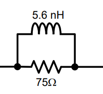
    I talked with my colleague and at high frequencies the inductor acts like a short circuit. At 200Mhz the total RL impedance of the equivalent circuit of the two circuit components below is 7 ohms. This is a 10 fold decrease from 75 ohm because of the inductor. Because of this, the full 750 to 11mvpp would show up on the SDI line while driving.


    If you would like to validate these results yourself, we suggest you purchase an EVM for the LMH1297. It works with 270mHz inputs and has an 800mVp-p at 75 ohms.

    Please let me know if there are any more questions.

    Best,

    Nick