This thread has been locked.

If you have a related question, please click the "Ask a related question" button in the top right corner. The newly created question will be automatically linked to this question.

DS100MB203: SCH review

Part Number: DS100MB203
Other Parts Discussed in Thread: DS110DF410

Dear TI Team:

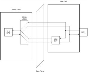
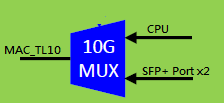
We have DS100MB203 in our design for 10G-KR mux application,

1. Pls review the SCH attached,Thanks

2. In datasheet, There are three functional mode,Pin control mode, SMBUS and external E2PROM,

So the functional mode just can be recognized through Pin_ENSMB when power up, right?

And if I pull RESET to low and then up when normal operation, this functional mode config can be re-recognized or not?

3. If in SMBUS mode, does it mean the level change of pin_SEL0 and pin_SEL1 will be ignored when normal operation, right?

4. If in pin control mode, does it mean the setting of EQ/DE will be fixed by the pull up and down resistor, and will be not changed when normal operation, right?

 7384.10G-KR mux.pdf

Best Regards

Lisa

  • Hi Lisa,

    I will review the schematic and provide feedback by EOD Friday 3/8.

    2. In datasheet, There are three functional mode,Pin control mode, SMBUS and external E2PROM,

    So the functional mode just can be recognized through Pin_ENSMB when power up, right?

    And if I pull RESET to low and then up when normal operation, this functional mode config can be re-recognized or not?

    I tested this behavior on bench and found that the functional mode (pin mode/SMBus slave mode/SMBus master mode) can be changed on the fly during normal operation. It is not necessary to power cycle the device or toggle the RESET pin to change the functional mode, you simply need to change the voltage level on the ENSMB pin.

    3. If in SMBUS mode, does it mean the level change of pin_SEL0 and pin_SEL1 will be ignored when normal operation, right?

    SEL0 and SEL1 pins are used to map inputs to outputs in both pin mode and SMBus modes. In SMBus modes, register settings can be used to override SEL0/SEL1 pin control.

    4. If in pin control mode, does it mean the setting of EQ/DE will be fixed by the pull up and down resistor, and will be not changed when normal operation, right?

    The EQ and de-emphasis settings can be changed on the fly during normal operation in pin mode. The device will continually read the voltage level on EQ and DEM pins during normal operation.

    Best,

    Lucas

  • Hi Lucas:

    Thanks for your kindly support, due to our boss highlight the project and customer information is confidential at currently stage, So now I cannot share the information to you, Need your understand.Thanks very much.

    Best Regards

    Lisa

  • Hi Lucas:

    I tested this behavior on bench and found that the functional mode (pin mode/SMBus slave mode/SMBus master mode) can be changed on the fly during normal operation

    ==>Does that mean I donot need has hardware pull up or pull down resistor for Pin48_ENSMB,Pin20_EQ_D0,Pin19_EQ_D1,Pin49_DEM_S0,Pin50_DEM_S1,Pin23_SEL0,Pin26_SEL1,

    Due to we can work in I2C mode and our ENSMB & SEL0 & SEL1 pin are connected to CPLD which can change level on the fly,

    Best Regards

    Lisa

  • Hi Lisa,

    Thanks for your kindly support, due to our boss highlight the project and customer information is confidential at currently stage, So now I cannot share the information to you, Need your understand.Thanks very much.

    I understand, thank you.

    ==>Does that mean I donot need has hardware pull up or pull down resistor for Pin48_ENSMB,Pin20_EQ_D0,Pin19_EQ_D1,Pin49_DEM_S0,Pin50_DEM_S1,Pin23_SEL0,Pin26_SEL1,

    That's correct, all of these pins can be set by CPLD instead of hardware pull-up/pull-down.

    I am in the process of reviewing your schematic and I have a few clarifying questions.

    1. Do you plan to switch between SMBus slave mode and pin mode? Can you share more details about when the functional mode will be switched?
    2. Will hardware pull-up/pull-down resistors be changed depending on when SMBus slave mode or pin mode is used?
    3. 10G-KR is a protocol specific to backplane applications. SFP+ modules are used in front-port optical applications. Do you intend to use 10G-KR with SFP+ modules?

    Best,

    Lucas

  • Hi Lucas:

    1. Do you plan to switch between SMBus slave mode and pin mode? Can you share more details about when the functional mode will be switched?==> It is the first time to use this component,so we have no plan how to control it or whether need switch on the fly or not at current stage, but I think we need reserve something in case furture need.
    2. Will hardware pull-up/pull-down resistors be changed depending on when SMBus slave mode or pin mode is used?==>Will no change if no other requirement or change, But I think the resistance for EQ/DQ will be changed to gurantee test pass when test dubug.
    3. 10G-KR is a protocol specific to backplane applications. SFP+ modules are used in front-port optical applications. Do you intend to use 10G-KR with SFP+ modules?==>Yes, and May I ask you a question, I try to find from web, but it seems I have not find the right material. For 10G-KR protocal, it is MAC-Phy architecture or not? And If yes, the SFP+ module connected to 10G-KR singal is acted as Phy or MAC?

    Best Regards

    Lisa

  • Hi Lisa,

    I understand, thank you for the clarifications regarding SMBus slave mode/pin mode and PU/PD resistors.

    Allow me to explain how a few common specifications fit into a typical 10G ethernet system. This application diagram comes from the DS110DF410 datasheet.

    • 10GBASE-KR (red arrow): This is an electrical specification with a backplane medium that fully defines the features and characteristics of a compliant ethernet PHY. 10G-KR includes support for link training and auto-negotiation protocols.
    • 10GBASE-R (red, blue arrows): This is a more general specification which defines PHY features and characteristics without focusing on a specific medium. 10G-R applies to both backplane applications (MAC <--> PHY) and front port applications (PHY <--> optical module or passive copper). 10G-R does not include support for LT and AN.
    • SFF-8431 (blue arrow): This specification defines the high speed and low speed host and module electrical specifications of SFP+ front port applications.
    • 10GBASE-SR (short reach), 10GBASE-LR (long reach), 10GBASE-ER (extra long reach) (green arrow): These specifications describe the requirements of an optical transceiver and do not provide the electrical requirements of a PHY that could drive the transceiver.

    Typically, we see customers implement DS100MB203 in 2 different places within a 10G ethernet system.

    • Backplane (between MAC and PHY): 10G-KR mode is used if link training and/or auto-negotiation are enabled. 10GE mode is used if LT and AN are disabled.
    • Front port (between PHY and optical module or passive copper): 10GE mode is used. SFP+ optical modules do not support LT and AN.

    As far as I'm aware, SFP+ modules always exist on the front port of the line card. I haven't seen any backplane (10G-KR) applications using SFP+ modules. Can you share a detailed block diagram showing how your application fits into a 10G ethernet system so I can better understand your intended use case?

    Best,

    Lucas

  • Hi Lisa,

    Here is my schematic review feedback.

    DS100MB203_Schem_Review.pdf

    Even though ENSMB, EQ, DEM pins can be controlled by CPLD only, I recommend keeping footprints for pull-up/pull-down resistors on these pins. This allows for final settings to be set by hardware once they have been determined.

    Best,

    Lucas

  • Hi Lucas:

    For this issue, I will check with Marvell, Then feedback to you If I get the reply.Thanks

    Best Regards

    Lisa

  • Hi Lisa,

    Sure, let me know when you get a response.

    Best,

    Lucas

  • Hi Lucas:

    Before I got the answer, Assume TL10---CPU use 10GKR, TL10---SFP+ use 10GE,

    How to set the mode pin of DS100MB203?

    And May I know what exactly different of  DS100MB203 when set mode to 0 and 1?

    Best Regards

    Lisa

  • Hi Lisa,

    I see 3 possible options to change the mode setting on the fly.

    1. Connect the MODE pin to the CPLD. Change the voltage level on the MODE pin at the same time you change the voltage level on the SEL0/1 pins. This will effectively change the mode setting when you change the input/output mapping.
    2. Tie 10G_MUX_SEL1 and/or 10G_MUX_SEL0 to the MODE pin through an inverter. When SEL0/1 = 0 (TL10 -- CPU), MODE = 1 (10G-KR). When SEL0/1 = 1 (TL10 -- SFP+), MODE = 0 (10GE).
    3. If you are using SMBus slave mode, you can override the MODE pin setting and configure the mode via register setting. Leave 0x08[2] = 1 asserted over the entire device duration (override MODE register bit). Mode setting can then be configured in 0x17[6] (D_OUT0), 0x25[6] (D_OUT1), 0x2D[6] (S_OUTA0), 0x34[6] (S_OUTB0), 0x3B[6] (S_OUTA1), and 0x42[6] (S_OUTB1).

    10G-KR mode: Configures the signal path as a linear redriver. Output is an analog representation of the input and EQ setting. Signal detect, de-emphasis, and VOD features are disabled. Linearity is necessary to support 10G-KR protocols (auto-negotiation and link-training).

    10GE mode: Configures the signal path as a limiting redriver. Output is only enabled when signal detect threshold is reached and does not follow analog behavior of the incoming signal. VOD and de-emphasis settings are applied on the TX driver to assist with meeting strict SFI eye mask requirements.

    Based on this description, I am assuming your use case leaves an option to bypass the PHY and directly connect the SFP+ module to the MAC? This should be possible if you can disable auto-negotiation and link training on your MAC, since SFP+ modules cannot support these protocols. If you wish to disable AN and LT when using the TL10 -- CPU configuration as well, then you can use 10GE mode at all times.

    Is this block diagram an accurate representation of your application?

    Best,

    Lucas

  • Hi Lucas:

    Best appreciation to you, your suggestion is very helpful for our product design.

    And we get reponse from marvell, it can support 10KR and 10GE, but need more SW effort to switch on the fly,It will cost much time.

    So I want to close this case at this time to avoid waiting long time for next process. Is it ok?

    Best Regards

    Lisa