This thread has been locked.

If you have a related question, please click the "Ask a related question" button in the top right corner. The newly created question will be automatically linked to this question.

DS90UB947-Q1: Identify serdes err, implement the interrupts.

Part Number: DS90UB947-Q1

Hi E2E,

When we design products, we need to match Deserializer IC such as DS90UB948.

We want to know how to recognize when a serdes error triggers an interrupt.

We see the combination function of INTB and INTB_IN, but we are not sure if the serdes error will cause Deserializer to PDB LOW.

Please help to explain how to identify serdes error triggered interrupt?

Thank you very much.

  • Hey Tommy,

    We see the combination function of INTB and INTB_IN, but we are not sure if the serdes error will cause Deserializer to PDB LOW

    There is no interrupt that will pull PDB low, that's something the SoC should be controlling. The interrupts are just flags to tell the controller an event has occurred and the controller takes care of servicing those flags based on the conditions detected. 

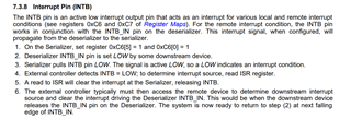
    INTB will trigger off of various local or remote interrupt status conditions. You can setup which status you want the interrupt to trigger off of through register settings. 

    Section 7.3.8 in the 947 datasheet goes over how to setup INTB. 

    Section 7.3.9 in the 947 datasheet explains how REM_INTB works. Basically the REM_INTB pin on the Ser side will mirror the INTB_IN pin on the Des side. So your external controller will be toggling the INTB_IN pin on the Des and that will be reflected on the Ser side through REM_INTB pin. This interrupt doesn't need clearing to go back to default status. It provides a pass-through of the INTB_IN signal from the attached Des to the Ser. 

    Also 948 datasheet goes over how the interrupts can be configured from Des side. 

    Regards,
    Fadi A.

  • Thanks for help.
    by the way, I would like to know whether there is a fault identification function in serdes?

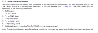
    Such as I2C communication failure, short circuit ,open circuit, overvoltage and so on

  • Hey Tommy,

    There are multiple ways to identify I2C failure on FPD-Link devices. For example, NACK is a control signal available at the I2C pins. If there is a problem with I2C access or if the I2C bus is busy, then a no acknowledge signal (NACK) is sent to the device starting the I2C transaction. 947 has registers 0x0A, 0x0B and 0x0C to check the back channel CRC errors to ensure the BC channel link is robust and no accumulation of errors or link issues present that could potentially impact I2C communication.  You're able to dump the register for the Ser and Des in a case of a failure mode and review the logs against the expected values to see what abnormal flags are set. If you're not able to readback the registers then that would also indicate an I2C issue so it really depends on the failure mode. As far as gross failures like short/open, etc. all of these could be identified by monitoring register 0x0C bit0 on the 947 side as explained in the datasheet. 

    Regards,
    Fadi A.