This thread has been locked.

If you have a related question, please click the "Ask a related question" button in the top right corner. The newly created question will be automatically linked to this question.

ONET1141L: Oper. Temp., modulation control, Feedback Gain from MPD

Part Number: ONET1141L

Hello There,

we use ONET1141L as laser diode driver for 10mW laser diode in closed loop feedback control though monitoring photo diode (MPD) built in the laser diode.

We use the laser driver for 100M transmitter circuit. We are aware of not characterized behavior at this speed as discussed here.

Q1: Temperature

Our application works in 85C electronics aluminum housing temperature: We read out from the laser driver 107C while housing temperature is being set to 85C. This is very close to absolute maximum ratings.

  • What is maximum operational temperature for reliability operation for 10 years?
  • Does the absolute maximum temperature mentioned in datasheet means the temperature on top of the case of ONET1141L OR/AND read out temperature from register?
  • What kind of heat sink do you recommend which may transfer the heat out of the chip? 

Q2: Modulation

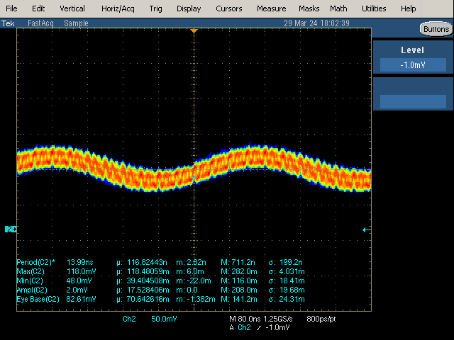
  • What creates the waving pattern on the output of the ONET1141L if NO modulation current is set?
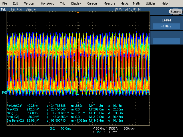
  • May this couple into the output if we have set the modulation current to extension ratio of 1/10 P0/P1?

Q3: Noise at monitoring photo diode

Built in monitoring photo diode with coupling efficiency of 0.25 mA / 10 mW of optical power.

With Photodiode range settings of register PDRNG we find out it works only if we use the large range of resolution: 1X: up to 3080μA / 3μA resolution. Any other ranges will created instability control loop in APC and corrupt data packets which increase Bit Error Rate.

  • What should be the settings for the MPD?
  • Is there a way to smooth output of the MPD by some external components?

Please find pictures of waving pattern with and without modulation current measured external PIN diode.

No Modulation current, PO = 6mW
Modulation current, PO = 6mW, bias ~ modulation current
Thanks 

Michael 

  • Hi Michael,

    1). Maximum recommended operating temperature is 100degC at thermal pad - i am thinking this same as board temperature. Do you have a mean to measure this?

    2). The waveform you've shown is this at OUT+/OUT- of the device? There seems to be some oscillation or un-stability causing this.

    3). I believe this observation was not seen on the EVM for this part. I can look for this EVM layout to correlate with your board. What are your thoughts on this?

    Regards, Nasser

  • Hi Nasser, 

    first of all thank you for your reply. 

    1. We will perform the measurement with thermal camera to check the correctness of measurement. What was the design approach for 100C? Running at 85C ambient at full power?
    2. The shown waveforms are optical output collected by illuminated external photodiode by Laser diode. This is a separate optical device. It is DET10A from Thorlabs.
    3. We checked the noise at other laser diodes and it is less significant. It seems that ratio of output optical power / MPD current helps. With large range it just decrease the problem not solve. 
      Do you think that some filter on the MPD helps? In worst we plan to close the feedback look through the MCU with at least moving average filter but it looses then the main advantage of the driver Onet1141L. 

    Thank you,

    Michael 

  • Hi Michael,

    1). I believe 85degC max operating temperature and at max power.

    3). It is possible. I looked at the electrical schematic and there is current mirror on PD pin with multiple jumpers to bias this point. I have attached a copy of this schematic.

    Also, there was an evaluation done with Eudyna EML TOSA. Please send me a friend request along with your company email so i can provide you this document.

    Regards, nasserONET1141L_HF_01202011.pdf