Other Parts Discussed in Thread: TPS25810, , TUSB1004
Tool/software:
CRES_Refresh_TUSB1142+TPS25810_SCH_0517.pdf
hi team,
please hlep with the sch check for TUSB1142 x3
regards,
Robin Liu
This thread has been locked.
If you have a related question, please click the "Ask a related question" button in the top right corner. The newly created question will be automatically linked to this question.
Tool/software:
CRES_Refresh_TUSB1142+TPS25810_SCH_0517.pdf
hi team,
please hlep with the sch check for TUSB1142 x3
regards,
Robin Liu
Hi Robin,
I reviewed the TUSB1142 in your schematic.
This review is for U3400, however all 3 devices seem to be implemented identically, so you can use this for the other two as well: TUSB1142 Review.pdf
One thing I was confused about is why you control the AEQENZ pin with the port controller? Is this intentional?

Best,
Shane
Hi Robin,
Sounds good, I'll mark this as resolved for now. Feel free to reply with any updates or questions and the thread will re-open.
Best,
Shane
https://e2e.ti.com/cfs-file/__key/communityserver-discussions-components-files/138/Brickyard_2D00_MB_2D00_BRD_2D00_20240624_2D00_U3400_2D00_U3600_2D00_U3800.7zCres Refresh TUSB1142+TPS25810 SCH Review_0619.pdf
hi Shane,
please help with the final sch and layout review.
and please reply me by PPT? Thanks~
regards,
Robin Liu
Hi Robin,
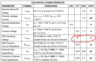
The 1142 looks correct in the schematic. One thing I noticed is that your ESD protection clamps at 9V:

I recommend using an ESD diode with a lower clamping voltage (closer to 3V is ideal). A device we typically recommend is the PUSB3FR4.
Here is my review of the layout: DELL_FXCNN_1142_layout_review.pptx
Let me know if you have any questions
Best,
Shane
hi Shane,
please hlep double check
https://e2e.ti.com/cfs-file/__key/communityserver-discussions-components-files/138/Brickyard_2D00_MB_2D00_BRD_2D00_20240703_5F00_USB_2D00_TYPE_2D00_c.7z
Cres Refresh TUSB1142+TPS25810 SCH Review_0703.pdf
regards,
Robin Liu
Hi Robin,
The ESD diodes look ok now. If the customer wants 8kV ESD protection, you can add 2 ohm resistors on the signal lines between the capacitors and ESD diodes as well.
The FLIP logic looks correct, as you have an inverter between the port controller and the 1142. This should align the MUX correctly with the active CC channel.
by the way, do you have TUSB1142 sch review checklist file?
We have a schematic helper tool for this part: 1142 schematic tool.pdf
It's not a full checklist, but can help when designing in the 1142. Is this what you had in mind?
Here is my review of the layout: 2450.DELL_FXCNN_1142_layout_review.pptx
A key question I have is what is the loss of your trace between the 1142 and the CPU? I see it is about 10in at the longest point, so I want to be sure your CPU and our re-driver have enough EQ compensation.
Best,
Shane
hi Shane,
for the tool, yes, but maybe you can share me a editable tool?
let me check with customer for the trace loss;
regards,
Robin Liu
Hi Robin,
I'm not sure the editable form will send correctly over E2E as it is in HTML format. I see we have an application note you can download that may better fit the customer's needs. This app note is a more detailed schematic checklist that covers both the TUSB1142 and the TUSB1004. Let me know if that works for you.
Looking forward to hearing the trace loss on this design.
Best,
Shane
Hi Robin,
Per the call last night, here is the excel version of the 1142 schematic checklist: TUSB1142 Schematic Checklist Excel.xlsx
Can you provide the list of devices DELL needs these checklists for?
Best,
Shane