This thread has been locked.
If you have a related question, please click the "Ask a related question" button in the top right corner. The newly created question will be automatically linked to this question.
Hi,
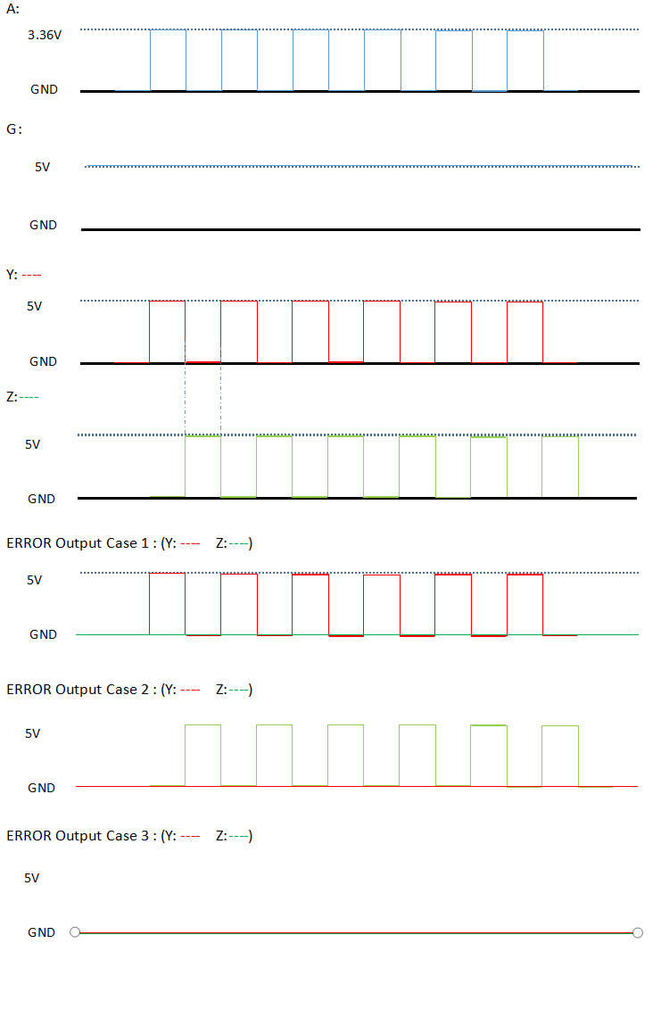
I use the AM26LS31C chip as the RS422 transmitter. The input of the AM26LS31C is the LVCMOS33 signals generated by FPGA. The schematic of the AM26LS31C as shown in the figure.
In the circuit testing, I found that OP1_EXT, OP2_EXT, OP3_EXT and OP4_EXT are LVCMOS33 square wave signals with a frequency of about 6KHz. However, at the output of the AM26LS31C, sometimes there is no signal at the Y OR Z,and sometimes there is no signal at both the Y AND Z.
I tested the operating temperature of the chip, which is between 40° and 60°.
When I replaced the chip supplier, the problem still exists.
Could someone please give me some advice on the use of AM26LS31x?
Best regards,
Penn
Hi Max,
Thanks for your reply.
For test the AM26LC31C, I used a counter in FPGA to generate a standard 6KHz square wave. And in order to rule out any PCB connectivity issues, I probe the signals directly at the IC pins.
I used USB to power up the system, the G directly connect to the USB power pin.
The most troublesome thing for me is that sometimes Y(Z) has a normal output and Z(Y) always stays low.
So I don't think I made a rookie mistake, Aha..
Regards,
Penn
Hi Hao,
I confirmed again, it is indeed the AM26LS31C.
There are a total of 4 chips on my board, any one of these 4 AM26LS31C, or any output channel of it, may output normal, or error like the above: error case 1, error case 2 or error case 3.
Regards
Penn
Penn,
Thanks for your confirmation. Do you see any patterns when error 1/2/3 happens? Could you check if it works better with the supply and ground both coming from one source? Although I don't think it would make any difference, could you try the tests with G=L as well?
Regards,
Hao