This thread has been locked.

If you have a related question, please click the "Ask a related question" button in the top right corner. The newly created question will be automatically linked to this question.

DP83822HF: DP83822 MII communication issue

Part Number: DP83822HF

Hi team,

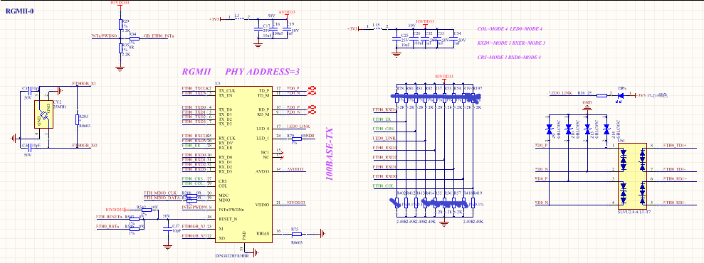
   We are penetrating DP83822 in their new project. Customer wants to know when using MII mode, can we capture clock signal in RX_CLK and TX_CLK?

And they are testing MII loopback, failed, the register 0x01's bit 2, link status didn't change, still 0. So Mac can't send data to PHY? Could you please help provide some advice to help solve this issue? Thanks.

  • Hi,

    I am not sure I follow your first question. 

    Please elaborate on this question.

    Please try forcing the PHY to 100Mbps Full-Duplex operation by setting register 0x0 to value 0x2100.

    Then set register 0x16 to the value 0x104 to force a digital loopback.

  • Hi Ross,

       I may still need your help to look into the first question, when PHY powers up, no any connection with MCU or DSP and no any operation, I cannot capture clock signal from RX_CLK and TX_CLK pin, but I can get it from our EVM.  So I think the PHY did not work normally.

       And the PHY did not works normally, how can I set the register value? Thanks.

  • Hi Lin,

    Please read register 0x0 to 0x1F and also register 0x467 and register 0x468.

    For 0x467/8, you will need to use extended register access:

    Write 0x1F to register 0xD

    Write 0x467 to register 0xE

    Write 0x401F to register 0xD

    Read register 0xE // value in register 0xE is the value in register 0x467

  • Hi Ross,

       I am still curious about the questions why we capture clock signal from RX_CLK and TX_CLK pin? If we cannot get signal from these two pins, how to read register value? Thanks.

  • Please see if the INT/PWDN pin is pulled low.

    Also check is there is voltage on VDDIO and AVD and Center Tap of the transformer.

    Do you have a clock source to the PHY?

    I suggest sending us your schematic for review.

  • Hi Ross,

       Thank you for your help here. First I want to check one thing, if the PHY power up normally, we should read register in the PHY, right? No matter the mode is RGMII or MII, right? Now the problem we faced is that we cannot read PHY register through MDIO! Thanks.

  • Hi Lin,

    You are correct.

    Please send a schematic so that we can review it and catch if anything is incorrect.

  • Hi Ross,

       Please see MII schematic below. Please help share me some suggestions to find the root cause. Thanks,

  • Hi Lin,

    Please DNP R401 and see if this resolves the issue.

    Are there any components that are DNP but not listed?

    What is the value of R520?

    Are all the bootstrap resistors stuffed or DNP or combination, if so which ones are DNP?

    Please ensure that RESET is above VIH.

  • Hi Ross,

       Thank you for your response here. Please see the my updates below,

    1.DNP R401 cannot solve this issue;

    2.For the strap pin, only COL, CRS,    and RX_ER have 1.96k pull down resistor. To set the MII mode and PHY address 0;

    3.R520=4.87k;

    4. Vreset=3.3V;

    Do you have any other suggestions for me to find the root cause? For we cannot read PHY address from MDIO. Thanks.

  • Hi Ross,

       Could you please help share your comments on this issue? Thanks

  • Hi team,

       Could you please help share me some suggestions to find the root cause? I have tried many methods but failed,

    1. Increase RESET capacitor to 1nF, failed;

    2. Remove INT pull down resistor, failed;

       I cannot capture RX_CLK and TX_CLK from our PHY and cannot read register from MDIO pin. We need your help to solve this issue quickly. Thanks.

  • Hi Lin,

    Can you please have them remove the series resistor on LED_1 please and test again.

    From the email you sent me, it looks like LED_1 is going into strap mode 2, which is a test mode.