A related question is a question created from another question. When the related question is created, it will be automatically linked to the original question.
If you have a related question, please click the "Ask a related question" button in the top right corner. The newly created question will be automatically linked to this question.
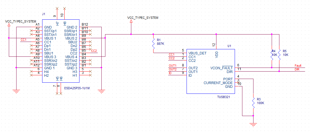
Since you are using TUSB321 in UFP mode, I recommend using OUT 1, OUT 2 and ID. To convene information to the AP or MCU. Since you are in a UFP only application then R2 is not necessary. This pin controls advertised current mode (only applied in DFP or DRP as host modes).
No in this case you do not have to have a PD controller. Please check the link below if you are unsure on when to choose a PD or CC controller. Yes, If a PD controller is connected over the CC line, CC negotiation will still occur but there will be no PD messaging after this.
Is there any more support needed for this issue? If so please reply with any relevant details so that I can further assist you. For now I will be marking this thread as "TI Thinks Resolved". If you have resolved your issue, please post the solution to the original problem/post for others with similar issues.