Part Number: TCAN1051HV-Q1
Other Parts Discussed in Thread: TCAN1051
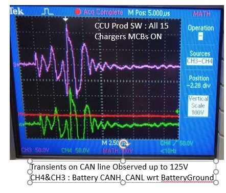
We have seen Both CAN FUSE open and ESD diode failure in field . In all cases this failure happened only during Charger Grid. attached block dia FYR Supply disconnection or making&Breaking.
[Edit] Removed attachment labeled "Confidential"