This thread has been locked.

If you have a related question, please click the "Ask a related question" button in the top right corner. The newly created question will be automatically linked to this question.

ISO3082: ISO3082 Part burnt

Part Number: ISO3082

Hello,

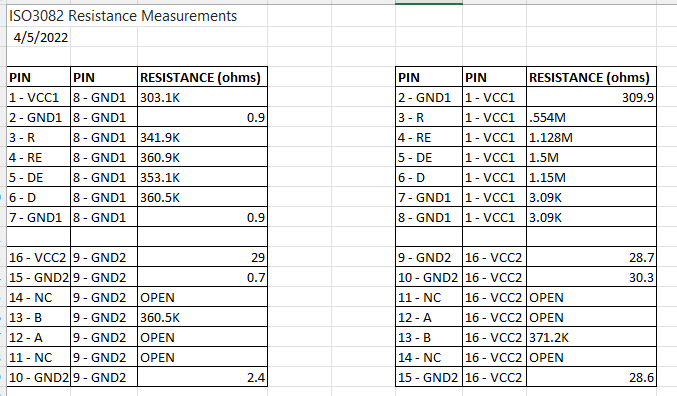
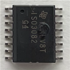
We encountered ISO3082 part failure per below pics 

Below is our schematics. We need to know the Root Cause asap for  our critical customer. I can't figure out how this will fail. Do you see any wrong value or anything in our schematics that can burn the device?

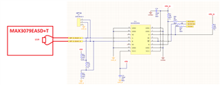
Let us know what data you need so we can get them for you.

Hope to hear from you soon.

Thanks,

Norman

  • Hi Norman,

    Sorry to hear about the issue.

    The schematic looks good, I do not see any issues. Please help us with below information to help debug the issue.

    1. Could you please confirm if the damage occurred during any specific tests? Like ESD or other EMC?
    2. What is the failure signature? Please share resistance of each pin with respect to their local GNDs. i.e., pins on VCC1-side with respect to GND1 and pins on VCC2-side with respect to GND2.
    3. Please also share PCB layout for review.
    4. How many samples tested and how many failed?


    Regards,
    Koteshwar Rao

  • Hi Koteshwar,

    Please see below:

     1. Could you please confirm if the damage occurred during any specific tests? Like ESD or other EMC?

    Norman: No ESD nor EMC test was conducted.

    2. What is the failure signature? Please share resistance of each pin with respect to their local GNDs. i.e., pins on VCC1-side with respect to GND1 and pins on VCC2-side with respect to GND2.

    Norman: We can provide resistance check as soon as it becomes available.

    3. Please also share PCB layout for review. 

    Norman: I cannot attach pics in this thread

    4.How many  tested and how many failed?

    Norman: 12 usage total and 2 failed same burnt mark.

  • Hi Norman,

    Thanks for sharing your inputs.

    3. Please also share PCB layout for review. 

    Norman: I cannot attach pics in this thread

    Please refer to the below 2 FAQ posts that describe how to attach an image or file.

    https://e2e.ti.com/support/site-support-group/site-support/f/site-support-forum/1016585/faq-easy-way-to-insert-screen-snippet-or-image-into-post

    https://e2e.ti.com/support/site-support-group/site-support/f/site-support-forum/761619/faq-how-do-i-attach-a-file-or-link-to-my-post

    Norman: We can provide resistance check as soon as it becomes available.

    I will look forward for the data, thanks.


    Regards,
    Koteshwar Rao

  • Hi Koteshwar, please see pin to pin resistance measurements for your reference. Please advise any idea for possible causes. thanks

  • Hi Norman,

    Thank you for sharing the resistance measurements of the damaged device.

    I can see that there is a short created between VCC2 and GND2 pins while the resistance looks good for all other pins. This can happen if there is any high voltage transient on VCC2 (+5V rail) or if there is steady voltage of >6V. It maybe possible that the +5V supply is creating this or some other section is adding such a transient to +5V rail.

    Other than this, I cannot think of any other possibilities to cause VCC2/GND2 short. To verify this, you can probably test further devices with a separate source for VCC2. You can also monitor VCC2 on an oscilloscope setting it in single-triggered mode to be triggered when the voltage exceeds 6V during all your testing. This will probably help you capture the transient and accordingly take actions to address it.

    Please do follow these steps to root cause the issue and let us know your observations. I will go ahead and mark this thread as closed now but you can also respond back to this once you are done with your testing or you can also create a new post. Thanks.


    Regards,
    Koteshwar Rao