This thread has been locked.

If you have a related question, please click the "Ask a related question" button in the top right corner. The newly created question will be automatically linked to this question.

LSF0108: Combining of LSF0108 and TXB0108 level shifters

Part Number: LSF0108
Other Parts Discussed in Thread: TXB0108, TXU0304, TXU0104, TXU0204, TXS0108E

Good day,

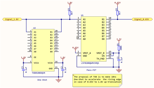
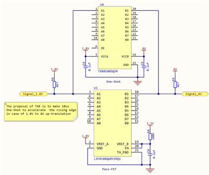
Is it allowable to combine the level shifters LSF0108 and TXB0108 as shown in 2 attached pictures?

Pict.1 - 0.65V <-> 1.8V translation

Pict.2 - 1.8V <-> 4V translation

(In the pictures only one line is connected to simplify the view)

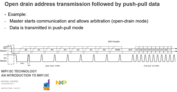
The proposal  of the schematic is to convert voltage level for I3C and SPI interfaces with freq. up to 33 MHz..

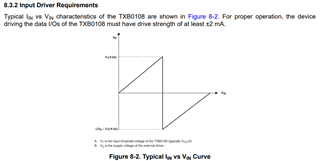
TXB0108 is added to LSF0108, because it is expected, that TXB0108 One-Shot function will decrease the rising edge time in case of up-translation.

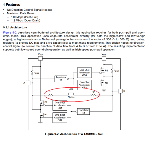
The idea of the suggested schematic based on the Architecture of a TCA39416 Cell which consists both: Pass-FET (like in LSF0108) and One-Shot (like in TXB0108).

  • The LSF and the TXB cannot be connected to each other; their outputs do not have enough drive strength for the other's inputs.

    For SPI, use the TXU0104/TXU0204/TXU0304. For I³C, you have to use the LSF alone.

  • I can not use TXU0104/TXU0204/TXU0304 because it is required the wider operating voltage range: from 0.65V to 4V. But TXU supports only above 1.1V.

    LSF has no predefined drive strength because it is a passive pass FET wo any amplification. So I suppose, that LSF drive strength is not exactly correct term.

    TXB drive strength is realy weak, because it has 4KOhm output impedance for its amplifiers. And it is the reason, why it is not recommended to use <20KOhm pullups with TXB.

    But in this schematic TXB is used only for one-shot function. The high impedance of TXB amplifiers is not a problem for the logic level holding, because here we have a Pass-FET on LSF. Please check the attached schematic once again. I suppose, that the question is little bit more complex than it seems at first glance.

     
  • I've never seen this before, but yes, the TXB could be used in this way to accelerate the edges. Please tell us how well it works in practice. :)

    In the second case, just use the TXS0108E instead.

  • Hello Aleksei,

    In addition to Clemens' response, I would also add here that the 4.7kohm pullups will result in a heightened VOL seen at the output of the TXB. If this is of concern, it is recommended that the pullup value to be greater than 50kohms to not contend with the internal 4kohm series driver.

    Effects of pullup and pulldown resistors on TXS and TXB devices

    Regards,

    Jack 

  • In these circuits, the TXBs have no effect on the DC levels of the circuits.

  • 1) I'll try to test the first schematic and will write how it works in this case :)

    2) Thank you for the advice. I need to transmit I3C signals, so at least 4MHz in open drain mode are required.

    But TXS supports only up to 1.2MBps open drain translation, so I can not use it.

    I think, that the reason of this TXS speed limit is a hign impedance of the pass N-channel, and the imposibility to add low-value pullup R on the line.

  • Hello Jack,

    Thank you for the info. I suppose that in case of setting LOW-level A and B sides will be connected directly via LSF pass-FET, and the pullup R will not make a high influence on the line voltage. In case of HIGH-level there isn't a level conflict with pullups.

  • Hey Aleksei,

    Thanks for realizing this gap with the TXS0108E- I will share this feedback with my team. 

    I see- the cascaded setup will also introduce more propagation delays between the I/Os, please make sure that it is within your system limits. I would also recommend having these two translators and their I/O devices as close as possible to minimize trace lengths in order to meet the required 33MHz. Please also ensure that section 8.3.2 is not in violation:

    Looking forward to your test results with this setup!

    Regards,

    Jack 

  • First schematic (LSF0108 + TXB0108(A/A) 1.8V-0.65V) doesn't work.

    Second schematic (LSF0108 + TXB0108(A/B) 1.8V-4V) works normaly.