Other Parts Discussed in Thread: SYSBIOS
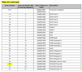
I am trying to use a capture control pin to measure the PWM of a input pin. I have read around and found that this is easiest using 2 pins, but sadly only have 1 on my current application. I'm using T0CCP0 to use timer 0A interrupt. The code looks like this:
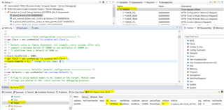
application.cfg setup to create HWI and switch internal clock to use timer3
var Clock = xdc.useModule('ti.sysbios.knl.Clock');
Clock.timerId = 3; /* use timer 3 */

var ti_sysbios_family_arm_m3_Hwi3Params = new ti_sysbios_family_arm_m3_Hwi.Params();
ti_sysbios_family_arm_m3_Hwi3Params.instance.name = "motorSpeedIntHandle";
Program.global.motorSpeedIntHandle = ti_sysbios_family_arm_m3_Hwi.create(19, "&MotorSpeedIntHandler", ti_sysbios_family_arm_m3_Hwi3Params);
pwm_measure.cc
extern "C" void MotorSpeedIntHandler() {
  static uint32_t pwm_fall_edge = 0;
  static uint32_t pwm_rise_edge = 0;
  static uint32_t log_counter = 0;
  // Timer has timed out
  if (TimerIntStatus(TIMER0_BASE, TIMER_TIMA_TIMEOUT) == TIMER_TIMA_TIMEOUT) {
      // If we timed out throw away sample
      pwm_fall_edge = 0;
      pwm_rise_edge = 0;
      TimerIntClear(TIMER0_BASE,  TIMER_TIMA_TIMEOUT);
  }
  if (TimerIntStatus(TIMER0_BASE, TIMER_TIMA_TIMEOUT) == TIMER_CAPA_EVENT) {
      int32_t pin_value = GPIOPinRead(GPIO_PORTL_BASE, GPIO_PIN_4);
      if (pin_value == 0) {
        pwm_fall_edge = TimerValueGet(TIMER0_BASE, TIMER_A);
        int32_t pwm_on_time = pwm_rise_edge - pwm_fall_edge;
        motor_speed_measured_RPM = (pwm_on_time / MOTOR_PWM_FEEDBACK_SPEED_CONVERSION_INVERSE);
      } else {
        pwm_rise_edge = TimerValueGet(TIMER0_BASE, TIMER_A);
      }
      TimerIntClear(TIMER0_BASE, TIMER_CAPA_EVENT);
  }
}

void motorControlFeedbackInit() {
  // Signal is a 482Hz from 5% - 100% duty cycle
  SysCtlPeripheralDisable(SYSCTL_PERIPH_TIMER0);
  SysCtlPeripheralReset(SYSCTL_PERIPH_TIMER0);
  SysCtlPeripheralEnable(SYSCTL_PERIPH_TIMER0);

  // Initialize timer A and B to count up in edge time mode
  TimerConfigure(TIMER0_BASE, (TIMER_CFG_SPLIT_PAIR | TIMER_CFG_A_CAP_TIME | TIMER_CFG_A_ACT_NONE));
  // 120MHz / 4 = 30MHz
  TimerPrescaleSet(TIMER0_BASE, TIMER_A, 4);

  // Timer a records pos edge time and Timer b records neg edge time
  TimerControlEvent(TIMER0_BASE, TIMER_A, TIMER_EVENT_BOTH_EDGES);

  TimerLoadSet(TIMER0_BASE, TIMER_A, 0xFFFF);

  //Configure the pin that the timer reads from (PL4)
  GPIOPinConfigure(GPIO_PL4_T0CCP0);
  GPIOPinTypeTimer(GPIO_PORTL_BASE, GPIO_PIN_4);

  TimerIntRegister(TIMER0_BASE, TIMER_A, MotorSpeedIntHandler);

  // Enable the indicated timer interrupt source.
  TimerIntClear(TIMER0_BASE, (TIMER_CAPA_EVENT | TIMER_TIMA_TIMEOUT));
  TimerIntEnable(TIMER0_BASE, (TIMER_CAPA_EVENT | TIMER_TIMA_TIMEOUT));
  TimerEnable(TIMER0_BASE, TIMER_A);
}
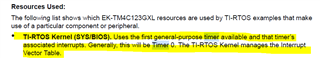
The problem I'm having, is as you see in the init function, I manually register an interrupt because it wasn't working through the .cfg once I register this interrupt(or unregister whatever one is already set) the RTOS crashes. I suspect that this is because the RTOS is using timer0 that it's doing something behind the scenes that registers it's own tick interrupt and doesn't like when I try to overwrite that. Am I missing something in the .cfg?
Thanks!