- Ask a related questionWhat is a related question?A related question is a question created from another question. When the related question is created, it will be automatically linked to the original question.
This thread has been locked.
If you have a related question, please click the "Ask a related question" button in the top right corner. The newly created question will be automatically linked to this question.
Part Number: TMS570LS1224PGE
Hi,
we currently have exactly the same problem as described in this thread:
Unfortunately no solution was provided there except "it should work this way".
We successfully set up ECAP reading with the example "example_etpwm_ecap". It works perfectly, even when duty cycle or period are changed slightly.
However, we want to capture a 67Hz, 3.3V PWM with a duty cycle of approx. 10-20%, which is very slow in comparison to the generated PWM from the example. In theory, it should be possible to capture signals of up to 53 sec period length before the counter overflows.
When trying to read our slow signal, all ECAP counters show the same values and thus we only get zeros as duty and period values. It seems like all capture events happen at the same time and a rising & falling edge are triggered at the same time.
We already generated our desired signal (and similiar ones) with different sources to be sure our signal source isn't the issue. The signals look fine in a scope.
Why doesn't the example work with low frequency signals? What needs to be done to read a relatively slow signal?
Best regards
Christian
/** @example example_etpwm_ecap.c
*   This is an example which describes the steps to configure ETPWM for generating PWM signal
*   and ECAP to capture the same and calculate its frequency and duty cycle,Here ETPWM1A pin is configured
*   to generate a PWM wave and is fed to ECAP1 pin.
*
*
*   @b Step @b 1:
*
*   Create a new project.
*
*   Navigate: -> File -> New -> Project
*
*   @image html example_createProject.jpg "Figure: Create a new Project"
*
*   @b Step @b 2:
*
*   Configure driver code generation:
*   - Enable ETPWM and ECAP drivers
*   - Disable others
*
*   Navigate: -> TMS570LS12x/RM46 -> Enable Drivers
*
*   @b Step @b 3:
*
*   Configure PINMUX to enable ETPWM1A and ECAP1 pins (or enable ETPWM and ECAP checkboxes)
*
*   Navigate: -> PINMUX -> Pin Muxing
*
*   Enable TBCLK sync
*
*   Navigate: -> PINMUX -> Special Pin Muxing
*
*   @b Step @b 4:
*
*   Enable ECAP1 Interrupt in VIM (Channel 104)
*
*   Navigate: -> TMS570LS12x/RM46 -> VIM Channel 96-127
*
*   @b Step @b 4:
*
*   Configure EPWM1A with specified duty and period
*
*   @image html etpwm_module_enable.jpg "Figure: Enable ETPWM modules"
*   @image html etpwm_config.jpg "Figure: EPWM1A configuration"
*
*   @b Step @b 5:
*
*   Configure ECAP1 as follows
*
*   @image html ecap_module_enable.jpg "Figure: Enable ETPWM modules"
*   @image html ecap_config.jpg "Figure: EPWM1A configuration"
*
*   @b Step @b 6:
*
*   Connect the pin ETPWM1A and ECAP1:
*
*
*   @b Step @b 7:
*
*   Copy the source code below into your sys_main.c or replace sys_main.c with this file.
*
*   The example file can also be found in the examples folder: ../HALCoGen/examples
*
*   @note HALCoGen generates an empty main function in sys_main.c,
*
*
*/

/*
* Copyright (C) 2009-2015 Texas Instruments Incorporated - www.ti.com
*
*
*  Redistribution and use in source and binary forms, with or without
*  modification, are permitted provided that the following conditions
*  are met:
*
*    Redistributions of source code must retain the above copyright
*    notice, this list of conditions and the following disclaimer.
*
*    Redistributions in binary form must reproduce the above copyright
*    notice, this list of conditions and the following disclaimer in the
*    documentation and/or other materials provided with the
*    distribution.
*
*    Neither the name of Texas Instruments Incorporated nor the names of
*    its contributors may be used to endorse or promote products derived
*    from this software without specific prior written permission.
*
*  THIS SOFTWARE IS PROVIDED BY THE COPYRIGHT HOLDERS AND CONTRIBUTORS
*  "AS IS" AND ANY EXPRESS OR IMPLIED WARRANTIES, INCLUDING, BUT NOT
*  LIMITED TO, THE IMPLIED WARRANTIES OF MERCHANTABILITY AND FITNESS FOR
*  A PARTICULAR PURPOSE ARE DISCLAIMED. IN NO EVENT SHALL THE COPYRIGHT
*  OWNER OR CONTRIBUTORS BE LIABLE FOR ANY DIRECT, INDIRECT, INCIDENTAL,
*  SPECIAL, EXEMPLARY, OR CONSEQUENTIAL DAMAGES INCLUDING, BUT NOT
*  LIMITED TO, PROCUREMENT OF SUBSTITUTE GOODS OR SERVICES; LOSS OF USE,
*  DATA, OR PROFITS; OR BUSINESS INTERRUPTION HOWEVER CAUSED AND ON ANY
*  THEORY OF LIABILITY, WHETHER IN CONTRACT, STRICT LIABILITY, OR TORT
*  INCLUDING NEGLIGENCE OR OTHERWISE ARISING IN ANY WAY OUT OF THE USE
*  OF THIS SOFTWARE, EVEN IF ADVISED OF THE POSSIBILITY OF SUCH DAMAGE.
*
*/

/* USER CODE BEGIN (0) */
/* USER CODE END */

/* Include Files */

#include "sys_common.h"

/* USER CODE BEGIN (1) */
#include "stdio.h"
#include "system.h"
#include "etpwm.h"
#include "ecap.h"
/* USER CODE END */


/** @fn void main(void)
*   @brief Application main function
*
*/

/* USER CODE BEGIN (2) */
/* USER CODE END */


void main(void)
{
/* USER CODE BEGIN (3) */

	_enable_interrupt_();

#if 1
	/* Initialise EPWM and ECAP with GUI configuration */
	etpwmInit();
	ecapInit();
#else
	/* Alternate code for configuring ETPWM and ECAP */
		/* Configure ETPWM1 */
	/* Set the TBCLK frequency =  VCLK4 frequency = 90MHz */
	etpwmSetClkDiv(etpwmREG1, ClkDiv_by_1, HspClkDiv_by_1);

	/* Set the time period as 1000 ns (Divider value = (1000ns * 90MHz) - 1 = 89)*/
	etpwmSetTimebasePeriod(etpwmREG1, 89);

	/* Configure Compare A value as half the time period */
	etpwmSetCmpA(etpwmREG1, 45);

	/* Configure mthe module to set PWMA value as 1 when CTR=0 and as 0 when CTR=CmpA  */
	etpwmActionQualConfig_t configPWMA;
	configPWMA.CtrEqZero_Action = ActionQual_Set;
	configPWMA.CtrEqCmpAUp_Action = ActionQual_Clear;
	configPWMA.CtrEqPeriod_Action = ActionQual_Disabled;
	configPWMA.CtrEqCmpADown_Action = ActionQual_Disabled;
	configPWMA.CtrEqCmpBUp_Action = ActionQual_Disabled;
	configPWMA.CtrEqCmpBDown_Action = ActionQual_Disabled;
	etpwmSetActionQualPwmA(etpwmREG1, configPWMA);

	/* Start counter in CountUp mode */
	etpwmSetCount(etpwmREG1, 0);
	etpwmSetCounterMode(etpwmREG1, CounterMode_Up);
	etpwmStartTBCLK();

	/* Configure ECAP1 */
	/* Configure Event 1 to Capture the rising edge */
	ecapSetCaptureEvent1(ecapREG1, RISING_EDGE, RESET_DISABLE);

	/* Configure Event 2 to Capture the falling edge */
	ecapSetCaptureEvent2(ecapREG1, FALLING_EDGE, RESET_DISABLE);

	/* Configure Event 3 to Capture the rising edge with reset counter enable */
	ecapSetCaptureEvent3(ecapREG1, RISING_EDGE, RESET_ENABLE);

	/* Set Capure mode as Continuous and Wrap event as CAP3  */
	ecapSetCaptureMode(ecapREG1, CONTINUOUS, CAPTURE_EVENT3);

	/* Start counter */
	ecapStartCounter(ecapREG1);

	/* Enable Loading on Capture */
	ecapEnableCapture(ecapREG1);

	/* Enable Interrupt for CAP3 event */
	ecapEnableInterrupt(ecapREG1, ecapInt_CEVT3);

#endif
    /*  ... run forever  */
    while(1);

/* USER CODE END */
}

/* USER CODE BEGIN (4) */
void ecapNotification(ecapBASE_t *ecap,uint16 flags)
{
	uint32 cap1, cap2, cap3;
	float64 duty, period;

	cap1 = ecapGetCAP1(ecapREG1);
	cap2 = ecapGetCAP2(ecapREG1);
	cap3 = ecapGetCAP3(ecapREG1);

	duty = (cap2 - cap1)*1000/VCLK4_FREQ;
	period = (cap3 - cap1)*1000/VCLK4_FREQ;

	printf("Duty = %fns\n", duty);
	printf("Period = %fns\n\n", period);

}
/* USER CODE END */Hi Christian,
Can you please reverify by reducing the VCLK3 clock frequency to 10Mhz?
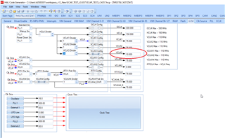
Because the time base counter in the eCAP module will be run from VCLK3 only, so if we reduce this frequency then we can measure low frequencies.
--
Thanks & regards,
Jagadish.
Hi Jagadish,
thanks for your reply.
We are using board TMS570LS1224PGE, not...1227.
I just changed VCLK4, which is used for calculation, and also VCLK3 to 10MHz.
It did not change the result.
We always get equal values for the different cap variables and thus no calculation of duty cycle or period is possible - see also attachment.
If we generate a faster signal, it works fine again.
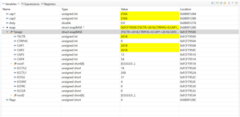
Hi Christian,
I understood the root cause for the issue you are getting.
Actually this issue is not due to the eCAP module actually it was due to the ETPWM module. I mean did you check whether you are getting 67Mhz output from
ETPWM module with oscilloscope?
Actually, ETPWM will not generate such low frequencies from 75Mhz Actual TB clock frequency. I tested in practical and find this issue.
To generate such low frequencies from ETPWM module we should adjust the pre-scalers as shown below:
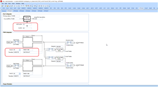
After adjusting pre-scalers as shown above then i got the 67Hz output waveform from ETPWM as shown below:

And as you can see now i got the capture register values for 67Hz input waveform:
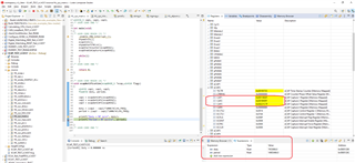
Here is my tested project for your reference:
Note: As i don't have TMS570LS12x board with me, so i did this testing with my TMS570LC43x Launchpad board.
--
Thanks & regards,
Jagadish.
Hi Jagadish,
thanks again for your reply.
We are not using the ETPWM module to generate the slow signal. We have tried the actual signal source (RC receiver) and also a signal generator and the capturing does not work with either of them. So the issue lies in the ECAP module. If we generate a fast signal above approx. 200 kHz, capturing works fine. If the signal becomes slower, below approx. 100 kHz, capturing does not work anymore.
Thanks for sharing the details.
I will try to check with other board and will provide you, my update.
Hi Christian,
I tested with RM46 board as well and this controller have same as the TMS570LS12x, and here also i didn't see any issues with 100Hz frequency output from ETPWM.
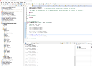
So, my suggestion would be this, please try to test with ETPWM signal once before testing with functional generators because it is a external oscilllators right there might be a grounding issues. So, please test with my code once and let me know the result of it, I am attaching my RM46 code for your reference.
--
Thanks & regards,
Jagadish.
Hi Jagadish,
thanks for your support. It is now working. First I tried to read a slow (100 Hz) signal generated by ETPWM pin, which worked fine.
Then we tried different signal sources and it did not work, exactly as before.
When we removed all printf commands and breakpoints and wrote the duty cycle and period to global variables, it started to work. So there seems to be some kind of timing problem caused by interruptions from printf and/or breakpoints causing this issue.
However, the issue is now solved, so thanks again.
Best regards
Christian