This thread has been locked.
If you have a related question, please click the "Ask a related question" button in the top right corner. The newly created question will be automatically linked to this question.
Tool/software:
Hello TI experts
SDK : motor_control_sdk_am243x_09_02_00_09
I noticed the support for BiSS safety is now available on the sdk above. I am having problem to configure BiSS to communicate to BiSS Safety encoder from Renishaw.
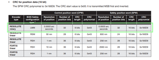
I am trying to communicate with Resolute rotary encoder as per the table below. Would you be able to provide guidance on the configuration steps to communicate with Resolute rotary encoder.
Thanks
Attached is full Data sheet
L-9517-9884-02-B_Data_sheet_BiSS_Safety_RESOLUTE_FORTiS_EN_TI.pdf
Alan I
A bit more details
I am able to communicate with above mentioned encoder using the normal non safety position.
My problem is on the safety data. I am not able to configure the BiSS controller to read safety data.
Thanks
Alan I
Alan
Can you share the steps you have tried for configuring the safety position?
Regards
Dhaval
Hi Dhaval
Renishaw BiSS Safety encoders runs in safety mode by default where control word and safety word are available on power-up. No additional configuration is required on the encoder side. In fact we can't read or write to any register on this encoder.
Using BiSS diagnostis example. These are the steps that I took
1- Specify No of Position Data Bits on startup 1st encoder single turn> 32
Multiturn > 0
Daisy Chain , 2nd encoder single turn > 0
2 - Execute command 3 | Encoder send position values
Encoder is able to return position with correct CRC
3- Since this encoder is by default in safety mode. I proceed to execute command 7 , Enable Safety Mode > 1
4- Execute command command 3 | Encoder send position values
Encoder-1 Singleturn Angle: 239.197067261000, received safety crc:0xaa18, calculated safety crc:0xc524, e_w:0x3, sign-of-life counter: 7
CRC Status: failure, crc error count: 1
Thanks
Alan I
Alan
Okay, we will check this and get back to you by next Tuesday.
Regards
Dhaval
Alan
Please note that the CPW and SPW is implemented by assuming 2 encoders connected in daisy chain (SPW will be sent by enc0 and CPW will be sent by enc1). So user has to provide 2nd encoder data length also according to the CPW data bit length.
Steps needed to be followed:
1) Enter enc0 data length corresponding to SPW data bit width -- SPW configuration - Menu option #1
2) Enter enc1 data length corresponding to CPW data bit width -- CPW configuration - Menu option #1 --> Assumption is CPW is sent as a second encoder response.
3) Enable safety using control communication - No need to perform this step if safety is enabled by default. - Menu option #6
4) Enable safety (for application purpose) by entering "1" for "enc0" and "0" for "enc1" as explained in sample log "BISS-C Sample Output when safety is enabled" - Menu option #7
5) Then request for position data - Menu option #3
Results need to interpret as: enc0 result is nothing but SPW and enc1 result is nothing but CPW.
This assumption is mentioned in https://software-dl.ti.com/processor-industrial-sw/esd/motor_control_sdk/am243x/09_02_00_09/docs/api_guide_am243x/BISSC_DESIGN.html under "Firmware Architecture" section while explaining the safety flow.
Regards
Dhaval
Hi Dhaval
Thank you for the guidance. I am now able to read encoder with safety.
Channel 0:
Encoder-1 Singleturn Angle: 263.392639160000, received safety crc:0xd0fe, calculated safety crc:0xd0fe, e_w:0x3, sign-of-life counter: 32
CRC Status: success, crc error count: 1
Encoder-2 Singleturn Angle: 263.392639160000, crc:0x27, otf crc:0x27, e_w:0x3
CRC Status: success, crc error count: 0
One other question on encoder numbering, it is meant to be reversed? If we look at data stream, I believed the BiSS Controller received CPW before SPW
Thanks
Alan I
Alan
One other question on encoder numbering, it is meant to be reversed? If we look at data stream, I believed the BiSS Controller received CPW before SPW
Can you share a logic analyzer/scope capture for the data stream for us to review?
Regards
Dhaval
Hi Dhaval
Sorry for late reply
I meant , if we look at protocol data stream.
CPW words are earlier than SPW words
Also, in real world application. Safety Encoder ( with both CPW+SPW) can be used in non-safe environment by reading only the 1st half of data stream which only contains CPW.
In BiSS Master FPGA documentation, the CPW and SPW are referred as 2 devices daisy chained together to form a single encoder.
Thank you
Alan I
Alan
In BiSS Master FPGA documentation, the CPW and SPW are referred as 2 devices daisy chained together to form a single encoder.
Yes, this is what we referred to and we have implemented the same.
I did not understand your question fully. Can you explain more on what do you mean by encoder numbering reversal here?
Regards
Dhaval
Hi Dhaval
Sorry for late reply
Using BiSS diagnotic safety option assume SPW in encoder 0 and CPW in encoder 1 which is in reverse to physical data stream sequence
Thanks
Alan I
Alan
We think the confusion is caused because of the way printing of results is being done. Due to the fact that our implementation supports daisy chaining as well as safety, our idea was to make the prints simple and compatible.
First assume 2 non safety encoders are connected in daisy chain then the data sent by encoders on the wire will be as follows:
[Data of enc2][EW of enc2][6-bit CRC of enc2][Data of enc1][EW of enc1][6-bit CRC of enc1]
From above 2nd encoder data will be received first and then 1st encoder data will be received but while printing the results we will print enc1 result and then enc2 result. As per daisy chain specification, although we receive the data of last encoder first, we print in the incremental order in the diagnostic application.
Now comes safety support. As we have implemented safety by assuming 2 encoders connected in Daisy chain encoder 2 will send CPW and encoder 1 will send SPW and on the wire the data will be as per spec:
[CPW][Data of enc2][EW of enc2][6-bit CRC of enc2][SPW][Data of enc1][EW of enc1][6-bit SOLC][16-bit CRC of enc1]
As we are reusing the daisy chain code, we are assuming CPW is sent as enc2 response and SPW sent as enc1 response and printing in the incremental order instead of CPW and SPW.
I also want to clarify that we are just printing the SPW first and CPW next but on the wire CPW is received first and SPW is received next only. Please do not get confused with the order of prints that is to have compatibility with actual daisy chaining of encoders.
Regards
Dhaval