Tool/software:
Hello, I use the TMS570LS3137 coprocessor to output PWM waveform, the code is as follows:
- L01 PWCNT { next=L02,hr_lr=LOW,cond_addr=L02,en_pin_action=ON,pin=20,action=PULSEHI,reg=NONE,data=0};
- L02 DJZ { next=PWM_IN_Duty1,cond_addr=L03,reg=NONE,data=0};
- L03 MOV64 { next=L04,remote=L01,en_pin_action=ON,cond_addr=L02,pin=20,comp_mode=ECMP,action=PULSEHI,reg=NONE,irq=ON,data=0};
- L04 MOV64 { next=PWM_IN_Duty1,remote=L02,en_pin_action=ON,cond_addr=L03,pin=20,comp_mode=ECMP,action=CLEAR,reg=NONE,irq=ON,data=0};
Under normal circumstances, this output PWM is no problem, but I found that if the main processor is changing the output of other HET pins (such as the main processor changes the output of HET4 and HET7 pins, and the coprocessor outputs PWM through HET20 pins), the output PWM will be incorrect at this time. I experimented with the following code (coprocessor code unchanged) :
- drvSetABSyn((FLOAT32)0.5, 700U);
- drvSoftwareDelaySomeMs(10000U);
- while(1)
- {
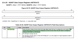
- hetREG1->DOUT &= (uint32)(~(((uint32)1U) << 4));
- hetREG1->DOUT |= ((uint32)1U) << 7;
- hetREG1->DOUT |= ((uint32)1U) << 4;
- hetREG1->DOUT &= (uint32)(~(((uint32)1U) << 7));
- }
The first line by modifying the coprocessor's memory output duty cycle of 50%, frequency of 700HZ PWM waveform, the second line delay 10 seconds, and then cycle control of the fourth and seventh pins of the HET. The final output is as follows:

Where the yellow line is the PWM waveform output by the HET20 pin, it can be clearly seen that the waveform is no problem before the main processor controls the HET pin, and the PWM is abnormal after the control.
What is the reason for this phenomenon? What's the solution?