This thread has been locked.

If you have a related question, please click the "Ask a related question" button in the top right corner. The newly created question will be automatically linked to this question.

TM4C1294NCPDT: Upgrade the firmware of custom board using UART and bootloader.

Part Number: TM4C1294NCPDT
Other Parts Discussed in Thread: ENERGIA

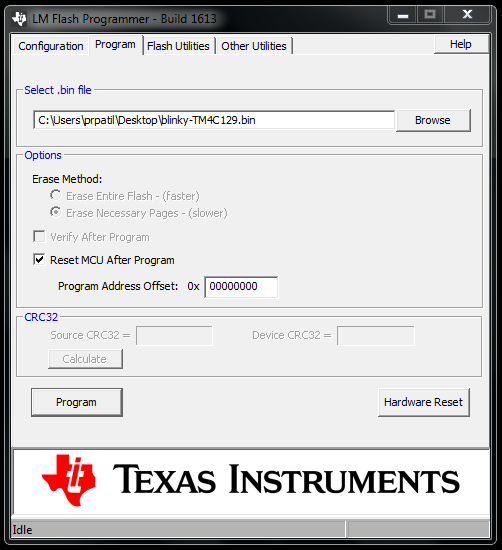
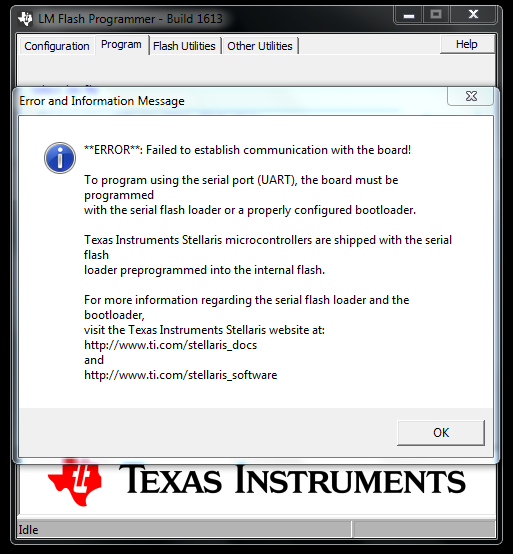
I have my custom board who's design is based on TM4C1294NCPDT. I want to upgrade the firmware of my custom board using UART and bootloader. I don't know the how to do that.

Any inputs/ insight /step by step guide that will help are appreciated.

  • And you installed a JTAG connector on custom PCB? Upgrade would seem to imply the flash has been previously written with application firmware?
  • Hello Techinspired,

    I would recommend start by looking at our TivaWare examples "boot_serial" and "boot_demo1" which will let you try on a LaunchPad a UART Bootloader example. Once you understand how the example works on the LaunchPad, then you can port that to your custom board as well. This would be the quickest and easiest way to learn about UART Bootloader with TM4C and get one running on your custom hardware.
  • BP101 said:
    And you installed a JTAG connector on custom PCB?

    Thanks for your reply....yes I've a JTAG connector on my custom PCB.

  • I've gone through both examples "boot_serial" and "boot_demo1". I was unable to completely understand the steps to dump the firmware on fresh custom board or upgrade it using a ROM based serial bootloader. Is there any document which would explain the steps in detail?

    Also I wanted to know can I use LM Flash programmer alone with out CCS and choose "Mannual Connection" in the LM flasher and choose "Serial(Uart)" and dump the bin file? If yes...Could you please explain me the connections ?

    Thanks.
  • Hi,

    Why not try a few things and see if it connects, recall LM with JTAG is useless.

    /cfs-file/__key/communityserver-discussions-components-files/908/SW_2D00_TM4C_2D00_BOOTLDR_2D00_UG_2D00_2.1.0.12573.pdf

  • Hello Techinspired,

    BP101 attached our Bootloader Guide which is the best resource we have in terms of documentation. You may find other E2E posts could be helpful too if you search around?

    As far as LM Flash Programmer, I don't think I've tried to use it for UART bootloader but the concept is the same as USB/Ethernet, you need to have your PC connected to the board UART port, make sure the UART is recognized by the PC (has a COM port), and then connect to that COM Port using LM Flash to load your .bin file.

    By the way regarding ROM bootloader, it will look at all supported interfaces until one of the interface receives a valid signal, it will then use that interface for the update.

    If multiple interfaces were detected, there is a sequence in which it chooses which is USB > ENET > I2C > SSI > UART.
  • Hi BP101,

    Thanks for your reply and doc.

    BP101 said:
     recall LM with JTAG is useless.

    I din't understand why you said that but I've programmed  an arbitrary MAC on my fresh custom board with the help of JTAG of TM4C123 board. So I was thinking to use" Serial UART" Connections.

  • Thanks Ralph for your reply!

    Ralph Jacobi said:
    you need to have your PC connected to the board UART port, make sure the UART is recognized by the PC (has a COM port), and then connect to that COM Port using LM Flash to load your .bin file.

    I'll connect UART0 pins that are PA0 and PA1 to USB to TTL board and connect that to my PC, and choose the "manual"connections and "Serial Port" in LM Flash Programmer to dump the .bin file.

    And second thing I wanted to ask the boot_demo1 example is also flash based bootloader(As I remember I've read it in comments)..I want a serial /uart  ROM based bootloder. As I have gone through another serial bootloader guide which demonstrates to use TM4C123 as a programmer device and the TM4C1294NCPDT as a target device. Now I don't have knowledge about: Should I include my firmware code with this examples of boot_demo1? or should I run them first then my firmware code?

    And  in "boot_serial" example, there is only bl_config.h where UART port is selected for communicating with bootloader. So how to run this boot_serial example with firmware...please explain.

    Also in the bootloader guide there are certain command for custom protocol for uart also...this and packet formation are needed in case of serial ROM based bootloader also?

    Thanks

  • Techinspired said:
    I din't understand why you said that

    Past tried to use XDS100 (JTAG header) with LM3S to write MAC user registers is not supported. The TMC123 board has an on board ICDI simulates (JTAG) control pins into the target and transports firmware or writes flash via USB CDM device drivers in Windows. That is not the same as using LM flash attempting to connect via JTAG header of custom PCB with an XDS100/200 JTAG simulator as any normal person would attempt to do after spending many $ on XDS simulator.

    I don't subscribe to the use of overly complicated TMC123 method to program a remote target TM4C129x. For that reason you are seemingly unaware CCS can direct connect to custom PCB via JTAG simulator and header to load firmware, debug it via SWO and use the register debug features built into CCS. One ideal high speed JTAG simulator (on a budget) is the XDS200 sold in the TI store and may become useful for knowledge gains down the road.

    The serial boot loader APP is a pain, adds complexity over that of invoking the embedded ROM version TM4C129x.

  • Hello Techinspired,

    The example in TivaWare does run in Flash because it is an example to help users learn. If you feel you have a good grasp on the bootloader using the flash version you can work on utilizing the ROM bootloader.

    Once you know what to do in terms of getting boot_demo1 into the board, I would say try to load the .bin for your own code as well so you have the location of the program setup the way you want. You wouldn't include the firmware in boot_demo1, but rather instead of loading boot_demo1, you'd load your firmware instead. The boot_demo1 just has functionality to jump to the flash bootloader repeatedly so you can see how you can trigger a bootloader via GPIO.

    Techinspired said:

    And  in "boot_serial" example, there is only bl_config.h where UART port is selected for communicating with bootloader. So how to run this boot_serial example with firmware...please explain.

    The boot_loader folder has the rest of the application. The bl_config.h file is the only one which should be edited, so that is why it is in the primary directory for the example.

    Techinspired said:

    Also in the bootloader guide there are certain command for custom protocol for uart also...this and packet formation are needed in case of serial ROM based bootloader also?

    Yes, you would need to use those for the ROM boot loader.

  • As per my understanding of  ROM uart boot loader is that it get involved only either BOOTCFG register's EN bit is clear or address at 0x4 is all F's, reference: 

    RTOS/TM4C129ENCPDT: Regarding bootloader - Arm-based microcontrollers forum - Arm-based microcontrollers...

    e2e.ti.com
    Part Number: TM4C129ENCPDT Other Parts Discussed in Thread: LMFLASHPROGRAMMER , UNIFLASH , EK-TM4C1294XL Tool/software: TI-RTOS Hi, We have built our USR-IoT

    Now my custom board was earlier programmed using TM4C123's ICDI so it's flash had to be erased( to invoke ROM based bootloader in LMFlash Pragrammer) so  I used the TM4C123's ICDI to erase flash.

    and checked that flash is  blank by blank check test which in my board case, was passed.

    Then I removed the JTAG connections and connected my custom board's PA0(RX) and PA1(TX) pin to USB to TTL board whice has COM port-9(who's baud rate I set to 115200 in device manager and kept the same baud rate in LM flash programmer too)

    and tried to program a blinky.bin to my custom board but it gave some error like this..

    Is there any important step of invoking uart ROM boot loader in LM Flash programmer, am I missing here? 

    Thanks.

  • Hello Techinspired,

    Sorry for the delay. I think you need to set the Program Offset before flashing the .bin file. This E2E thread discusses that: e2e.ti.com/.../2013487
  • Hello Ralph,

    Thanks for your reply!

    Few things I want to ask:

    1) Can I test this whole bootloader process on launchpad who's UART0 pin's are not out on the header. So the debug cable would work for UART0? so the COM port in LM flash programmer would be the debug com port of launchpad...right? and what other jumpers should I remove/ mount?

    2) Do I need to program the boot_serial.bin in between, after the flash has been erased and the application bin is going to be programmed?

    3) What does the "boot_serial" example do?

    4) If I set the #define APP_BASE 0x2000 in the linker cmd file, so I would be entering the same offset address in the program offset address
    field in LM Flash programmer too? But in the bl_config.h the APP_START_ADDRESS is defined as 0x4000 not as 0x2000...so this thing is
    confusing.

    5) If I need to set the program offset in linker cmd file then this is doable in case of a project built in ccs but my application has been built in
    in Energia so where do I set/find linker cmd file,BTW I have imported energia code in ccs and dumped the application using JTAG.

    Regards.

  • Hello Techinspired,

    1) You can test the whole process on a LaunchPad through the ICDI USB port. The UART interface will be visible to the LM Flash programmer, allowing you to program it just like you would if you had a UART to USB translator to connect to the PC. So correct, the COM Port in LM Flash Programmer is the Debug COM Port of the LaunchPad. You don't need to remove any jumpers as long as the power source is selected to be ICDI and the CAN/UART headers are setup for UART.

    2) You can program boot_serial.bin at any point, no need to erase flash first. You can program it from CCS as well.

    3) It is a Flash Bootloader. You can configure it for each of the various bootloader examples by modifying the .h file. It's basically an all-in-one project for each possible serial protocol Flash bootloader (UART, I2C, SPI, CAN, and USB).

    4) You need the define for your APP_BASE in your Linker to match the define for the APP_START_ADDRESS in the bl_config.h file. This is also the offset you need to indicate in the LM Flash Programmer for the "Progream Address Offset: 0x" box.

    5) I have no idea about how Energia would work with all of this. I would recommend trying to use a CCS example first just to make sure you have the UART Bootloader part down, and then ask on the Energia forums about how they do bootloader applications with it and where you can modify the APP_BASE address.
  • Hello Ralph,

    Thanks a lot for your elaborate explanation and help!

    Though, I have not tested this whole boot loader process on Launchpad or on my custom board, as I'm caught up in another issue of not getting IP address for my custom board so this task has taken precedence over the "uart bootloader" task....but as soon as I sort out the IP address issue(which I've posted on this forum also...hoping to get a solution/help here, as I've been struggling with this issue for a while. Could anyone from hardware design team from TI help me in this regard?) I will test the serial bootloader later and will keep you posted about the update.

    Best Regards,
    Techinspired

  • Perhaps this might be of service: i.imgur.com/LFHuP3J.png

    Shows a TM4C1294NCPDT dev board connected to another as debugger/programmer. It's actually what I use to program my prototypes ^_^
    It's not too much hassle to whip up a little ribbon cable connector to 10 pin plug for on-the-go use.

  • HI

    you have to load  "boot_serial" example using JTAG. Once it is running it will download boot_demo1.bin via LM flash programmer. Please refer to the TivaWare boot_serial (the boot loader) and the boot_demo1.bin (the application) examples.

  • Prachi Patil said:
    ....but as soon as I sort out the IP address issue(which I've posted on this forum also...hoping to get a solution/help here

    Hi Prachi,

    Thanks for the verified! 

    Curious did your custom PCB get IP address yet. Many seem to end up in forum posting EMAC0 can't pull IP address. Perhaps send link to post via PM if still having issues, best of luck this New Year to get it working.