Part Number: MCU-PLUS-SDK-AM261X MCU-PLUS-SDK-AM263PX
Hello Experts,
I need to implement a standalone EtherCAT MDevice(MainDevice) on TI AM2x series MCU devices. My issue is where will i get a master stack to run on it?
Also will there be some sample MDevice stack with the board available for testing purposes? Could you please provide sample code?
Thanks
Part Number: AM2634-Q1
Currently, the MCAL projects seems to be a makefile based environment and how to use CCS studio to create, compile and debug our MCAL based projects easily? We're seeing lot of errors regarding missing assembly and source files. How to solve this?
How to edit the linker.cmd file to add new sections in TCM and how to add the application code into these TCM sections for faster code execution?
Part Number: TMS570LC4357
Part Number: TMS570LC4357
After CPU has updated the data buffer, but the DMA still transfers the old content in the buffer instead of the updated one.
Part Number: TMS570LC4357
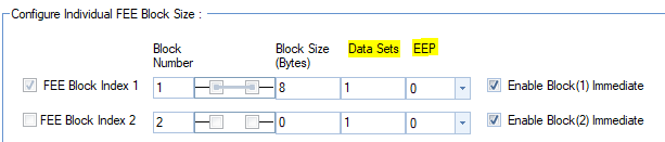
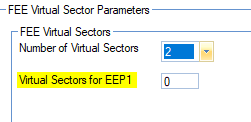
To generate FEE drivers from Halcogen software I had some questions about the highlighted parameters shown in images below. I read the Technical Reference Manual of TMS570LC4357 but didn't get much details about these parameters.
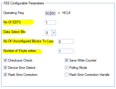
1. What is "EEPS"? How to decide the value of this parameter?
2. What are "Data Select Bits"? How to decide the value of this parameter?
3. Use of "No. of unconfigured blocks to copy" & How to decide the No. of unconfigured blocks to copy?
4. What is "Number of 8 bytes writes"? How to decide value of this parameter?
5. How to decide "Data Sets" value for particular FEE block index?
6. How to decide "EEP" value for particular FEE block index?
7. What is EEP1 & EEP2? How to decide value of "Virtual Sectors for EEP1"?
What is the recommended production method of loading an flash device during mass production?
Part Number: TMS570LS1224
The Hercules microcontrollers protect all accesses to the on-chip flash memory and on-chip SRAM memory by dedicated Single-Error-Correction-Double-Error-Detection (SECDED) logic. The access to the program memory (bank 0 or bank 1) and SRAM is protected by SECDED logic implemented inside the ARM Cortex-R4F CPU. Accesses to the EEPROM emulation flash bank (bank 7) are protected by dedicated SECDED logic inside the flash wrapper.
1. ECC Memory Space for BTCM Interface is 0x0840_0000. During Cortex-R4 read access from ECC BTCM Space, if there is a Double Bit Error detected by Cortex-R4, will there be a data abort?
2. ECC Memory Space for ATCM Interface is 0xF040_0000. During Cortex-R4 read access from ECC ATCM Space, if there is a Double Bit Error detected by Cortex-R4, will there be a data abort?
3. ECC Memory Space for EEPROM Bank7 Interface is 0xF010_0000. During Cortex-R4 read access from ECC Bank 7 Space, if there is a Double Bit Error detected by Cortex-R4, will there be a data abort?
Part Number: TMS570LC4357
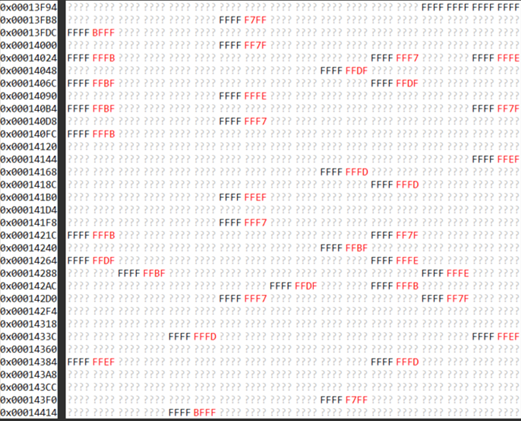
After the flash is erased, why the flash content doesn't become 0xFFFFFFFF?
Part Number: TMS570LC4357
1. How to enable those three temperature sensors?
2. Can the temperature sensor be used to measure the room temperature?
3. How to configure the pin multiplexing to select AD1IN[31] for the temperature sensor 1?
4. How to configure the pin multiplexing to select AD2IN[31] for the temperature sensor 2?
5. How to configure the pin multiplexing to select AD2IN[30] for the temperature sensor 3?
6. How to calculate the junction temperature from the three sensors' value?
