This thread has been locked.

If you have a related question, please click the "Ask a related question" button in the top right corner. The newly created question will be automatically linked to this question.

TMS320F28388D: use the DP83867 in 10/100 mode with the F28388?

Part Number: TMS320F28388D
Other Parts Discussed in Thread: C2000WARE, DP83620, DP83640

Hello Guys,

Good day.

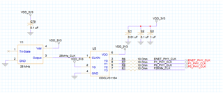
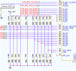
Our customer have a question about the F28388DZWTS. He saw the errata about using a gigabit phy for the ethercat.  He used the  DP83867IRPAPT.  He also used this for the ethernet.  He saw that the F28388 does not support gigabit ethernet.  Can you  still use the DP83867 in 10/100 mode with the F28388?

Thanks and regards,

Art

  • Hello Guys,

    Just like to update regarding this.

    Thanks and regards,

    Art

  • Hello ART,

    Sorry for the delayed response here.

    Can you pls point me to the exact errata that you are referring to and the silicon version as well ?

  • Hello Karthikeyan,

    Below are the information from the customer:

    TMS320F2838x Real-Time MCUs Silicon Errata Silicon Revisions A, 0
    SPRZ458D – MAY 2019 – REVISED MAY 2021

    The EtherCAT Slave Controller configures the PHY registers assuming it is gigabit- capable. This may result in undesirable PHY operation if a non-gigabit PHY is used.
    Use a gigabit PHY.

    Thanks and regards,

    Art

  • Hi,

    Still its not clear on whether your question is pertaining to Ethernet or EtherCAT(ESC).

    Secondly, this errata is applicable only for EtherCAT(ESC) that too Rev-0. If a giga-bit phy is used for EtherCAT(ESC) in Rev-0 silicon, then there is a chance it might malfunction. But this issue does not exist with EtherCAT(ESC) in Rev-A.

    This is not applicable for Ethernet in both versions.

    Hope its clear.

  • Thanks Karthikeyan. I might direct customer to this thread so that he will be able to explain his use case better.

    Thanks and regards,

    Art

  • Hello Art and Karthikeyan

    We still have a number of questions about connecting to the TMS320F23388D.

    We are using Rev-A chips. When we connect to the controlCard, which uses the 83822’s, we do show a connection and can see the phy’s over TwinCAT. On our board with the 83867’s however, we do not see a connection. The hardware lights do not show a connection either. We are using the f2838x_cpu1_pdi_hal_test_app project provided in the C2000Ware_3_03_00_00 package unmodified in both cases. The only difference is that we have to declare the symbol “USE_20MHZ_XTAL” when connecting to the ControlCard. We do not use this symbol when connecting to our development board. Debugging on our Board shows that the C28x is in the while loop in the file pdi_test_app.c that begins on line 77, which indicates that the EEPROM has not been programmed yet. So it was able to get through the setup stuff for the EtherCAT Phys in the ESC_initHW() function. Debugging on the ControlCard shows that it is also at this same “while loop” waiting for the EEPROM to be programmed. The supply voltages have been tested and are correct on the board. We are able to talk to the chips with MDIO as well, indicating that they are indeed powered on.

    For the Ethernet would the DP83640 or the DP83620 work as an alternative to the 83867? Is the F28388D simply just incompatible with the 83867? Testing on our end results in the 83867 failing on the Ethernet_initInterface() function, specifically waiting for the Software Reset to be performed in Ethernet_resetModule().

    In regards to the C2000Ware_3_03_00_00, specifically the Ethernet drivers provided, should these work with the DP83640, DP83620, and the DP83867 when connected to the F28388D?

    Thanks for your time,

    Ed

  • Hello Edward, Art,

    The subject matter expert best able to answer is out of office this week.  Please expect a delay in response - you should hear back by Monday.  Thank you for your understanding. 

    Best Regards

    Lori

  • Hello Lori,

      Thank you, I am looking forward to hearing back from them Monday.

    Regards,

    Ed

  • Thank you Edward - apologies I hit the wrong button! I didn't mean to set TI thinks resolved.   The thread is still open. 

  • Hi Ed,

    I believe the DP83867 should work OK for EtherCAT, even though it has Gigabit capability. It might be worth asking the question on the interface team's forum as well since they probably have some ideas of things you can check or test (https://e2e.ti.com/support/interface-group/interface/f/interface-forum).

    In regards to the C2000Ware_3_03_00_00, specifically the Ethernet drivers provided, should these work with the DP83640, DP83620, and the DP83867 when connected to the F28388D?

    Ethernet / EtherCAT software should be PHY agnostic, MII interface will need be used with the F2838x. Are you using the same signals to the PHYs as the F28388D controlCard?

    How are you clocking the F2838x device and PHYs on your custom board? The PHYs and ESC should use the same clock source.

    Best,

    Kevin

  • Hello Kevin, 

    I just verified this again this morning, I am using the same signals as the controlCard.  The clock signals are from the same source.

    Regards,

    Ed.

  • Hi Ed,

    Your clocking scheme looks fine and matches what we have on the F2838x ContorlCard.

    I'd recommend taking a look at the ECAT PHY selection App Note Beckhoff has, linked below. There is a section 'Gigabit Ethernet PHYs used for EtherCAT' that mentions restricting to 100 Mbps speeds.

    https://download.beckhoff.com/download/Document/io/ethercat-development-products/an_phy_selection_guidev2.7.pdf

    I notice that DP83640 and DP83620 are listed, but not DP83867. This doesn't necessarily disqualify the PHY for EtherCAT however.

    Best,

    Kevin

  • Hi Kevin and Art,

      When strapping to 10/100 mode does the Autoneg disable have to be set to 1?  Here is my current strapping.

  • Hi Edward,

    Sorry, I'm not sure. I'll move this post over to the Interface forum and they should be able to answer what's required by the DP83867 for 10/100 Mbps mode.

    Best,

    Kevin

  • Hi Edward,

    Autonegotiation should remain enabled for 10/100 mode. ANEG_SEL0 and ANEG_SEL1 should both be set to 1. This corresponds to mode 3 or 4 for pins RX_D4 and LED_1. The strap on RX_D4 looks correct, but I can't see your strap circuit for LED_1.

    Thanks,

    Lucas

    All information in this correspondence and in any related correspondence is provided “as is” and “with all faults”, and it is subject to TI’s Important Notice (http://www.ti.com/corp/docs/legal/important-notice.shtml).

  • Hello Art, Kevin and Lucas,

      I am still missing something.  I have combined all applicable parts onto one schematic page.  Please see attached .pdf

    etherCAT.pdf

    Regards,

    Ed

  • Hi Edward,

    I'm reviewing your schematic and will provide feedback by Wednesday.

    Thanks,

    Lucas

    All information in this correspondence and in any related correspondence is provided “as is” and “with all faults”, and it is subject to TI’s Important Notice (http://www.ti.com/corp/docs/legal/important-notice.shtml).

  • Hi Edward,

    Here are my notes after reviewing your schematic:

    • I recommend adding a 10uF cap on each supply for bulk decoupling.
    • I noticed rbias is 4.75k on ethercat P1 PHY. This is a PHY critical connection and needs to be 11k.
    • Can you confirm that your clock meets datasheet requirements?
    • Is the net on the reset pin of the ethernet PHY mislabeled? It currently says TX_ERR. Please also make sure that the host drives reset high during normal operation on all PHYs.
    • Can you share your magnetics/RJ45?
    • Which MAC interface do you want to use on each PHY? I'm confused because the straps on ethercat P0 and P1 PHYs disable RGMII, but there are no net labels on COL, CRS, or RX_D4-D7.
    • Why are you using PU/PD resistors on RX_ER/GPIO and COL/GPIO for ethercat P0 and P1 PHYs? There aren't straps on these pins for the 64 pin package.
    • Can you confirm that want the ethernet PHY to advertise 10/100 speed?

    Thanks,

    Lucas

    All information in this correspondence and in any related correspondence is provided “as is” and “with all faults”, and it is subject to TI’s Important Notice (http://www.ti.com/corp/docs/legal/important-notice.shtml).

  • Hi Lucas,

      Please see attached pdf.

    • There are 10uF capacitors on each supply shown on this schematic, these were located on another page in the original schematic.  
    • P1 PHY has a 11K.  The label was incorrect, but I verified the part and part# was correctly placed on the board.  I also verified the voltage at that pin.
    • The clock is supplied by 3.3V, we have a 27pF capacitor divider on each PHY, that was not shown on the original attachment.  The waveform of the clock signal looks clean and is below the MAX P-P voltage and within 10ppm.
    • The magnetics are built in to the connector, Pulse Electronics JXD2-0015NL.  I use this same connector on all three places.  Please see the Image above the ETHERCAT_IN connector.
    • RGMII.  The resistors for disable where removed.
    • The PU/PD resistors on RX_ER and COL where a mistake and have been removed from the schematic and board.
    • I have tried all the combinations of speed.  It was suggested here, to try 10/100.
    • We still do not show a connection in software or hardware. 

    UpdatedEthercat.pdf

    Thank you,

    Edward.

  • Hi Edward,

    I recommend using the following isolation between PHY gnd and shield gnd for best emi/emc performance, however this won't be critical to the connection issue.

    Can you probe RX_CLK, CLKOUT, and MDI link pulse lines? Can you also read registers 0x0, 0x1, 0x10, 0x11, 0x6E, 0x6F and tell me their values?

    Thanks,

    Lucas

    All information in this correspondence and in any related correspondence is provided “as is” and “with all faults”, and it is subject to TI’s Important Notice (http://www.ti.com/corp/docs/legal/important-notice.shtml).

  • Hi Lucas,

    I'm one of the Software Programmers working with Ed. We were able to get the register values after several resets.

    • BMCR (0x00) - 0x1140
    • BMSR (0x01) - 0x7949
    • PHYCR (0x10) - 0x5848
    • PHYSTS (0x11) - 0x0002
    • STRAP_STS1 (0x6E) - 0x8820
    • STRAP_STS2 (0x6F) - 0x0140

    Ed got the following points when he measured the lines:

    • RX_CLK was a 2.50 MHz square wave. 3.50 Vp-p and 2.07 Vrms.
    • CLKOUT was a 25.0 MHz square wave. 3.91 Vp-p and 1.97 Vrms.
    • XI was a 25.0 Mhz square wave. 1.59 Vp-p and 911 mVrms.
    • MDIO was high.
    • MDC was low.

    Were the MDIO and MDC Lines what you were referring to when you asked us to probe the MDI link pulse lines?

    We noticed that the Ethernet_init still hangs on the Ethernet_resetModule() function in ethernet.c waiting for the Soft Reset to be

    completed.

    We also noticed that sometimes it takes several resets of the board in order for the MDIO interface to return non-zero values.

    Thanks,

    Joseph

  • Hi Joseph,

    I noticed some of the reserved bits in the strap register were changed from default values. Can you try adding a 2.4k PD on LED_0 to force the strap to mode 0?

    MDI link pulse is sent over the RJ45 to search for a link partner. Since port mirroring is enabled, this will happen on channels C and D. Can you probe these channels?

    Thanks,

    Lucas

    All information in this correspondence and in any related correspondence is provided “as is” and “with all faults”, and it is subject to TI’s Important Notice (http://www.ti.com/corp/docs/legal/important-notice.shtml).

  • Hi Lucas,

    We fixed some resistors on our end, which corrected the Port Mirroring appearing enabled the LED0 Strap.

    Here are the new register values:

    • BMCR (0x00) - 0x1140
    • BMSR (0x01) - 0x796D
    • PHYCR (0x10) - 0x5048
    • PHYSTS (0x11) - 0x7C02
    • STRAP_STS1 (0x6E) - 0x0000
    • STRAP_STS2 (0x6F) - 0x0140

    Plugging an Ethernet Cable into each of the Ports and into our Computer now shows an established connection in the "Network Connections" Pane in Windows 10. The updated register values also reflect that auto-negotiation was able to complete and that a valid link was formed. Which is good!

    However, the Ethernet code still gets stuck performing a Software Reset with the Ethernet_resetModule() provided in C2000Ware. The EtherCAT chips show up as "Device 1" on TwinCAT, which is incorrect according to the EtherCAT Slave Controller Software User Guide provided in C2000Ware.

    Do you have any ideas why this would be happening?

    Thanks again for your help!

    Joseph Keene

  • Hi Joseph,

    How are you calling the software reset? Does writing 4000 and 8000 to register 0x1F cause the same freeze? Does performing a hardware reset do the same?

    Thanks,

    Lucas

    All information in this correspondence and in any related correspondence is provided “as is” and “with all faults”, and it is subject to TI’s Important Notice (http://www.ti.com/corp/docs/legal/important-notice.shtml).

  • The Software Reset is performed in ethernet.c, provided in the C2000Ware as part of the driverlib_cm folder. Here is the snippet.

    /*These Routines are functions that touch the Ethernet Registers */
    void Ethernet_resetModule(uint32_t base)
    {
        //
        //DMA Initialization
        //
        HWREG(base + ETHERNET_O_DMA_MODE)  =  ETHERNET_DMA_MODE_SWR;
        //
        //Wait till the Soft Reset is done
        //
        while((HWREG(base + ETHERNET_O_DMA_MODE) &  ETHERNET_DMA_MODE_SWR) ==
            ETHERNET_DMA_MODE_SWR)
            {
            }
    }
    

    The code gets stuck in the while loop waiting for the DMA to clear the ETHERNET_DMA_MODE_SWR flag.

  • Hi Lucas,

    Looking at the register description in the TRM, specifically "Table 43-324. DMA_MODE". Bit 0 of the Register corresponds to the Software Reset that is currently hanging up. Here is what is describes about bit 0 in the TRM (TMS320F2838x TRM):

    Software Reset
    When this bit is set, the MAC and the DMA controller reset the logic
    and all internal registers of the DMA, MTL, and MAC. This bit is
    automatically cleared after the reset operation is complete in all
    DWC_ether_qos clock domains. Before reprogramming any
    DWC_ether_qos register, a value of zero should be read in this bit.
    This bit must be read at least 4 CSR clock cycles after it is written to
    1.
    Note: The reset operation is complete only when all resets in all
    active clock domains are de-asserted. Therefore, it is essential that
    all PHY inputs clocks (applicable for the selected PHY interface) are
    present for software reset completion. The time to complete the
    software reset operation depends on the frequency of the slowest
    active clock.
    Access restriction applies. Setting 1 sets. Self-cleared. Setting 0 has
    no effect.
    0h = Software Reset is disabled : 0x0
    1h = Software Reset is enabled : 0x1

    From what I understand, if the code hangs in the while loop waiting for this bit to clear, then is must be some sort of issue with the PHY clocks, correct?

  • Hi Joseph,

    Just to confirm, are you programming the processor to pull the reset pin low? Or are you programming the registers for a software reset? What register are you referring to where bit 0 isn't self clearing?

    Thanks,

    Lucas

    All information in this correspondence and in any related correspondence is provided “as is” and “with all faults”, and it is subject to TI’s Important Notice (http://www.ti.com/corp/docs/legal/important-notice.shtml).

  • Hi Lucas,

    The register is the DMA_MODE_REGISTER, which is a part of the Ethernet Media Access Controller (EMAC) of the F2838x.  The register is described on page 4810 of the TRM. See attached link. F2838 TRM. The register in question exists on the Ethernet Module that is a part of the Processor.

    Thanks,

    Joseph Keene

  • Hi Joseph,

    Is the issue still seen if you program the PHY register 0x1F with 4000 or 8000 for a software restart or reset?

    Thanks,

    Lucas

    All information in this correspondence and in any related correspondence is provided “as is” and “with all faults”, and it is subject to TI’s Important Notice (http://www.ti.com/corp/docs/legal/important-notice.shtml).

  • Hi Lucas,

    We were probing the signals from the PHY and noticed that the RX CLK was outputting a signal at 25 MHz but the TX CLK wasn't outputting anything. Figure 20. MII Connections on the Datasheet for the DP83867 (link: DP83867 Datasheet) shows that the TX CLK is supposed to come from the PHY to the MAC when operating in MII Mode. What could be causing the TX CLK to not be outputting?

  • Hi Joseph,

    We are looking into your question and will be able to provide feedback by Thursday of this week.

    Thank you,

    Nikhil Menon,

    Applications Engineer | Ethernet

    All information in this correspondence and in any related correspondence is provided “as is” and “with all faults”, and it is subject to TI’s Important Notice (http://www.ti.com/corp/docs/legal/important-notice.shtml).

  • Hi Nikhil,

    We were able to solve our problem following your advice in this forum post: DP83867IR: MII only mode, TX_CLK stays low. We set the RX_D6 Strap to Mode 3, effectively setting register 0x32 to all 0's by enabling RGMII_DISABLE. Once we did that, our TX_CLK read 25 MHz.

    We are now able to send and receive packets using our Ethernet PHY. We still aren't able to connect the two EtherCAT PHY's to Beckhoff's TwinCAT. TwinCAT discovers them as Device Type 1, not Type 2. If you guys have any ideas why this might be, we would appreciate any advice!

    Thanks,

    Joseph Keene

  • Hi Joseph,

    I'm glad to hear that the TX_CLK issue has been resolved! Our team is looking into your question and will be able to provide feedback by tomorrow latest.

    Thank you,

    Nikhil

    All information in this correspondence and in any related correspondence is provided “as is” and “with all faults”, and it is subject to TI’s Important Notice (http://www.ti.com/corp/docs/legal/important-notice.shtml).

  • Hi Nikhil,

    Just wanted to see if you were able to find anything!

    Thanks,

    Joseph Keene

  • Hi Joseph,

    Apologies for the delay. We should check that the settings required for EtherCAT are enabled. Is the fast link drop feature enabled?

    Thank you,

    Nikhil

    All information in this correspondence and in any related correspondence is provided “as is” and “with all faults”, and it is subject to TI’s Important Notice (http://www.ti.com/corp/docs/legal/important-notice.shtml).

  • Hi Nick,

    We currently have the fast link drop strapped to disable. Should it be strapped to enable?

    Thanks,

    Joseph Keene

  • Hi Joseph, 

    Yes Fast Link Drop should be enabled. Could you kindly remind me which version of the DP83867 is this?

    Additionally you may find the requirements for EtherCAT in this app note: https://www.ti.com/lit/an/snla344a/snla344a.pdf?ts=1631313963318&ref_url=https%253A%252F%252Fwww.google.com%252F

    The app note details how to configure the DP83826 for EtherCat, though the same rule and principles will apply for the DP83867.

    Please let me know if you have any further questions.

    Thank you,

    Nikhil

    All information in this correspondence and in any related correspondence is provided “as is” and “with all faults”, and it is subject to TI’s Important Notice (http://www.ti.com/corp/docs/legal/important-notice.shtml).

  • Hi Nikhil,

    Thank you for the application note. I will add a new question or post if we are still struggling.

    Joseph

  • Hi Joseph,

    Thanks for the reply. Please do create a new query with a link to this post if you have any further questions. I will be closing this thread.

    Thank you,

    Nikhil

    All information in this correspondence and in any related correspondence is provided “as is” and “with all faults”, and it is subject to TI’s Important Notice (http://www.ti.com/corp/docs/legal/important-notice.shtml).