- Ask a related questionWhat is a related question?A related question is a question created from another question. When the related question is created, it will be automatically linked to the original question.
This thread has been locked.
If you have a related question, please click the "Ask a related question" button in the top right corner. The newly created question will be automatically linked to this question.
Hi Team,
Would you kindly assist with the inquiry below?
A customer developed a custom board with the TMS320F28022PTT after programming a LAUNCHXL-F280049C. They encounter no issue programming the board, but they got a stuck-at-zeros faults when trying to test the connection between the CCS and the board through the LAUNCHXL on board XDS110. They have removed the shunts from J101 on the LAUNCHXL, They use a breakout board with the cable from J102 to the appropriate signals on my board. they placed the F28022 into Wait Mode by pulling GPIO37 high before powering it on. After that they applied power, then removed the pull up on GPIO37, and tried manually pulling XRS low with a jumper. After this they attached the LAUNCHXL via J102, already with power on and connected to CCS. the target configuration set to F28022 on CCS for XDS110, with cJTAG and SWD off. nTRST is registering as ~2.9 V with a 10 kR pulldown, and XRS is high, but the test connection always fails with the scan path stuck-at-zero issues.

here is the link to the pin out reference: https://software-dl.ti.com/ccs/esd/documents/xdsdebugprobes/emu_jtag_connectors.html
I hope you can help. Let me know if you need more information.
Regards,
Marvin
Here is my understanding of the issue:
Is the above correct?
After that they applied power, then removed the pull up on GPIO37, and tried manually pulling XRS low with a jumper.
I presume the F28022 is a new device with a blank flash. If so, you can attempt to connect to the device in Wait-mode itself. No need to bring it out of Wait mode. Also, no need to manually reset the device, since there is an on-chip POR circuitry.
nTRST is registering as ~2.9 V with a 10 kR pulldown,
-TRST should be normally low (in standalone functional mode), but this pin will be driven high when the JTAG debug probe tries to take control of the device (via CCS). Not sure why this is at 2.9v.
Please provide the wiring diagram between J102 and F28022. I hope you have connected the grounds of the two boards together.
Please refer to www.ti.com/lit/SPRACF0 for debug tips.
Hi Hareesh,
Good day and thanks for the response.
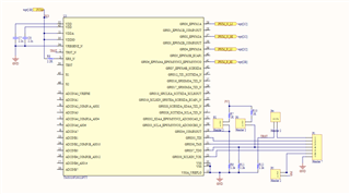
you are correct, the jumpers on J101 are removed, and then use only an ARM 10 pin cable attached to J102 to debug, while supplying power to the board separately. From the 10-pin cable, three grounds are connected to the custom board ground, and the TMS, TCK, TDO, TDI, and nRESET signals to the appropriate pins on the F28022, as shown in the schematic. nRESET has a 10k pulldown on the board and is normally low, but upon connecting the debug cable it goes high. Key and VTRef are left unconnected.
In addition, the JTAG lines may be more than 6 inches, but I would imagine that would affect signal integrity, and would not be responsible for the stuck at zero faults, is this a safe assumption to make?
Regards,
Marvin
You haven't provided the wiring diagram between J102 and F28022.
but I would imagine that would affect signal integrity, and would not be responsible for the stuck at zero faults, is this a safe assumption to make?
Yes.
I checked with the JTAG experts and received the following feedback: “The ‘XDS_RESET_OUT’ on the LaunchPad isn’t the same as -TRST signal and hence cannot be used to debug devices that need a -TRST signal”.
Hi Hareesh,
would the onboard XDS110 on the launchpad have a TRST signal on the chip itself making it possible to tap the pin with some fine gauge wire? If not will the programmer TMDSEMU200-U help?
would the onboard XDS110 on the launchpad have a TRST signal on the chip itself making it possible to tap the pin with some fine gauge wire?
No.
If not will the programmer TMDSEMU200-U help?
Yes.