This thread has been locked.
If you have a related question, please click the "Ask a related question" button in the top right corner. The newly created question will be automatically linked to this question.
Hi Team,
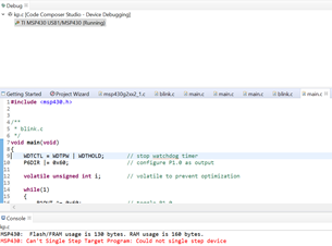
I am using a custom board with MSP430F5438 and MSP-FET debugger with latest CCS complier.
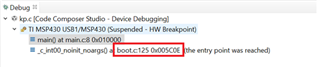
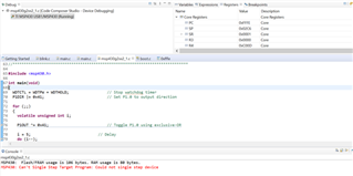
I am able to flash the program to MSP430F5438 using MSP-FET and i am not able to step in to debug mode.
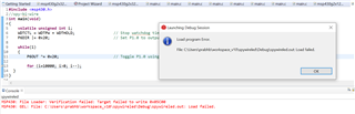
When i try entering the debug mode i am getting a error as "Can't single step target program: Could not single step device".
I tried the below options and still getting the same error.
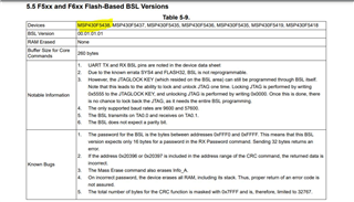
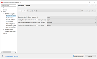
Based on different e2e post i tried as per figure 2.1 and 2.3 from - https://www.ti.com/lit/ug/slau278ah/slau278ah.pdf.
I also tried with JTAG cable length with less than 20 cm even then getting the same error.
Please help me to resolve this issue.
Thanks
Prabhu
Hi Prabhu,
Have you checked the erratasheet? There are several errata related to single-stepping over code in debug mode.
Hi James,
I checked the Errata sheet and i could not find any clue for the issue stated above. Please help.
Thanks,
Prabhu K
What is the optimum value of pull down resistor should be connected at the test pin of MSP430F5438. (refer fig 2.1 of https://www.ti.com/lit/ug/slau278ah/slau278ah.pdf.)
Did you read through Note F below Figure 2-1? It gives a range of values you can pick from.
yes i added 750 ohm and i was able enter into debug mode and was not able to debug the entire coding.
#include <msp430.h>
//#include "io430.h"
int main( void )
{
WDTCTL = WDTPW | WDTHOLD; // stop watchdog timer
volatile unsigned int i; // volatile to prevent optimization
P6DIR = 0x20; // Making port 6 output ports
while(1)
//for(;;)
{
P6OUT ^= 0x20; // toggle P6.5 & P6.6
for(i=10000; i>0; i--) // delay
}
}
upon debugging observed the following.
1. It was not entering the while loop, and popped up "Can't single step target program: Could not single step device".
2. with while loop commented, and used the infinite for loop, it came down and popped up the error at the inner for loop [for(i=10000; i>0; i--) // delay] and popped up the error "Can't single step target program: Could not single step device".
Could you please let me know what am I missing.
Note: only after connecting the pull down resistor i was able to enter into debug mode. Hence request your comment on the optimum value of pull down resistor.
Thanks
Prabhu K.
If you had to add a pull down resistor to TEST, then I think that's a clear indication that there's excessive noise on your custom board. This may be affecting the debug session. Even though you said it didn't help resolve your issue, I would strongly suggest using very short connections (< 20 cm) moving forward. Keep in mind that length assumes you don't have long traces on your custom board.
I would compare your JTAG circuit to Figure 2-1 in the MSP430 Hardware Tools User's Guide. I suspect you need to lower the value of the C1. Try reducing it to 1-nF.
Other than that, I'm not sure what else to recommend. I assume that if I used a MSP-FET and tried to debug your code on a target board for the MSP430F5438, I probably wouldn't see this issue. Thus, I suspect your issue is a noise/hardware issue.
Hi James, thanks for the information.
I would like to share you some additional information on spy-bi-wire programming.
When i tried with spy-bi-wire, i am getting the following error.
Request your input on the above error code.
Note: i have not tried with the reduced capacitance of 1nF. will try and update you the results.
Thanks for the update. I hope reducing the capacitance will help resolve the issue. Another thing you could try is deleting the debug configurations by creating a new CCS workspace, import a F5438 code example from the TI Resource Explorer inside CCS and try to download/debug the code on your device.
Also, let me point out that the F5438 device is not recommended for new designs. Consider using the F5438A in your final design instead.
Hi James, thanks for your inputs. i reduced to the cable length to less than 5 cm and changed the capacitance value to 1nF in the custom board. still facing the same issue.
Please note that our custom board design is based on the following link.
i could see there is no pull down resistor (on page 24 ) in the above link on the test pin, but whereas in fig 2-1 of MSP430 Hardware Tools User's Guide (Rev. AH) (ti.com) i could see the pull down resistor.
Please help me to understand and resolve this issue.
Thanks,
Prabhu K.
Hi James, thanks for your inputs. i reduced to the cable length to less than 5 cm and changed the capacitance value to 1nF in the custom board. still facing the same issue.
I'm glad to hear you made these changes, even if they didn't fix the issue.
i could see there is no pull down resistor (on page 24 ) in the above link on the test pin, but whereas in fig 2-1 of MSP430 Hardware Tools User's Guide (Rev. AH) (ti.com) i could see the pull down resistor.
The pulldown resistor on TEST is optional.
Please help me to understand and resolve this issue.
Are your compiler optimization settings on the lowest settings?
Look at the schematic for the MSP-EXP430F5438 again and the datasheet to see if you're missing any other important connections or are using the wrong capacitor values. Connections like VCORE are extremely important.
Does this happen on more than one device?
Are you exceeding the max current supply from the MSP-FET?
When i tried with spy-bi-wire, i am getting the following error.
Why don't you try using 4-wire JTAG?
I'm not sure what else to recommend at this point. If possible, please share your MSP430 portion of the schematic.
Hi James, Can you please share the timing diagram for F5438 controller. It will help me to identify whats wrong with my custom board.
Can you please share the timing diagram for F5438 controller.
I'm not sure what you mean. Do you have any feedback on my latest questions? Did you go over them?
Hi James,
Are your compiler optimization settings on the lowest settings? Not sure what do u mean by lowest settings. Please help me on how to check this settings.
Look at the schematic for the MSP-EXP430F5438 again and the datasheet to see if you're missing any other important connections or are using the wrong capacitor values. Connections like VCORE are extremely important. - On comparing the Eval board schematics and custom board schematics, i could not find any difference.
Does this happen on more than one device? I tried with only one board. I have one more PCBA, i can check on that.
Are you exceeding the max current supply from the MSP-FET? Actually its a Legacy PCBA, during its operation itself its current will not exceed 30mA.
Why don't you try using 4-wire JTAG? I always used to test it with 4-wire JTAG. Just checked for its working in spy-bi-wire.
I programmed MSP430G2553 using MSP-FET and i am was able to debug, in the mean time I probed the reset, TDI, TDO, TMS, TCK, Test pins and compared with the waveform with my custom PCBA. And I see there is difference in the waveforms. Hence asked you for the MSP430F5438 JTAG signals waveforms to compare and check with my custom board waveforms.
Note: I am not allowed to share the schematics and waveform here.
Hi James, additional information's.
Please see the below image from the debug window. Please check if something can be inferred from the below image.
Soon after the build, controller starts to execute the coding. Its not getting into the debug mode. Upon activating step into button, the following error occurs.
Please note that, custom board which I have now is from production with loaded application software. Before we purchased the MSP-FET, tried to read some values through UART. Now I suspect when reading through UART, accidently will that have modified BSL and might locked the JTAG? (https://www.ti.com/lit/ug/slau319ae/slau319ae.pdf?ts=1628502999808 page 41)
if you suspect that JTAG might be locked, please help me with the procedure to unlock it.
Thanks and Regards,
Prabhu K.
Are your compiler optimization settings on the lowest settings? Not sure what do u mean by lowest settings. Please help me on how to check this settings.
In CCS, you can change the optimization settings by right-clicking on your CCS project and then clicking Properties > CCS Build > MSP430 Compiler > Optimization. For debugging, I would recommend using an optimization level of 0 (register optimizations) and a setting of 1 for the speed vs. size trade-offs. Make sure you click "Apply and Close" and then rebuild your project.
Look at the schematic for the MSP-EXP430F5438 again and the datasheet to see if you're missing any other important connections or are using the wrong capacitor values. Connections like VCORE are extremely important. - On comparing the Eval board schematics and custom board schematics, i could not find any difference.
That's good to hear. Thanks for checking.
Does this happen on more than one device? I tried with only one board. I have one more PCBA, i can check on that.
It's always good to check on more than one F5438 device/board. When you programmed the G2553, that demonstrates that your toolchain and MSP-FET are working correctly.
Are you exceeding the max current supply from the MSP-FET? Actually its a Legacy PCBA, during its operation itself its current will not exceed 30mA.
That's also good to confirm.
Why don't you try using 4-wire JTAG? I always used to test it with 4-wire JTAG. Just checked for its working in spy-bi-wire.
Okay.
I programmed MSP430G2553 using MSP-FET and i am was able to debug, in the mean time I probed the reset, TDI, TDO, TMS, TCK, Test pins and compared with the waveform with my custom PCBA. And I see there is difference in the waveforms. Hence asked you for the MSP430F5438 JTAG signals waveforms to compare and check with my custom board waveforms.
If all the connections are correct, then capturing these waveforms isn't typically necessary. Unfortunately, I don't have access to this device at the moment. Instead, I would recommend using a new F5438 device to ensure the original device hasn't been damaged.
Note: I am not allowed to share the schematics and waveform here.
No problem. This is a public forum.
Soon after the build, controller starts to execute the coding. Its not getting into the debug mode. Upon activating step into button, the following error occurs.
This sounds like the debug session starts just fine in CCS. I would consider that debug mode. Make sure your optimization settings are low.
Please note that, custom board which I have now is from production with loaded application software. Before we purchased the MSP-FET, tried to read some values through UART. Now I suspect when reading through UART, accidently will that have modified BSL and might locked the JTAG? (https://www.ti.com/lit/ug/slau319ae/slau319ae.pdf?ts=1628502999808 page 41)
This is interesting. As you can see in the Notable Information section in Table 5-9, the BSL is not reprogrammable. Also, JTAG can be locked and unlocked one time only.
if you suspect that JTAG might be locked, please help me with the procedure to unlock it.
If you can download code onto the device in CCS and run to main() in a debug session, then the JTAG interface wouldn't be locked.
As I mentioned earlier, try using a new F5438 device to see if the issue is resolved.
Hi James,
Thanks for your reply.
I tried to reproduce the same error with G2553 eval kit and i am successful in reproducing it by changing the processor option.
Please see the below images on the changes made to processor option to reproduce the error.
Note: i had made this setting by comparing the default setting of msp430F5438 processor option.
In msp430F5438, i checked the optimization level was at 0 and speed vs size trade-off was at 1. And the --use_hw_mpy was set to F5.
it would me much helpful if you provide some information related to silicon version msp vs mspx. For msp430f5438 what should be be silicon version.
could you please confirm the processor option settings for MSP430F5438 and what should be set for -use_hw_mpy in optimization settings . Based on your input i will check for debug with same controller and then will try with a new controller.
Note 2: In G2553 eval kit, i could see the difference in performance when -use_hw_mpy is set to 16 and none. Request your inputs on the -use_hw_mpy for MSP430F5438 controllers.
Also request your inputs on PC, at what address it initially starts when the controller enters into debug mode for MSP430F5438.
Thanks in advance.
Thanks and Regards,
Prabhu K.
I tried to reproduce the same error with G2553 eval kit and i am successful in reproducing it by changing the processor option.
That's strange. We definitely don't recommend using a different microcontroller option than the actual device excluding devices in the same family with just memory size variations.
Could this indicate that your device is different than MSP430F5438? Is it actually MSP430F5438A? Typically, CCS will show a warning indicating that the selected device doesn't match the target device.
it would me much helpful if you provide some information related to silicon version msp vs mspx. For msp430f5438 what should be be silicon version.
The CPUX core supports 20-bit addressing. The device-specific user's guide should have more details.
could you please confirm the processor option settings for MSP430F5438 and what should be set for -use_hw_mpy in optimization settings . Based on your input i will check for debug with same controller and then will try with a new controller.
Note 2: In G2553 eval kit, i could see the difference in performance when -use_hw_mpy is set to 16 and none. Request your inputs on the -use_hw_mpy for MSP430F5438 controllers.
Either setting should work for MSP430F5438. It has a hardware multiplier whereas the MSP430G2553 does not. You can learn more about the compiler settings by referring to the MSP430 Optimizing C/C++ Compiler User's Guide.
Hi James,
Thanks for your reply.
i just wanted to share that if we use a wrong settings then it would cause the error. Hence i suspect that some setting for MSP430F5438 is wrong in my complier. can you please share the preferred setting for MSP430F5438.
My custom board has MSP430F5438 only.
Getting confused in processor option (silicon version) which one should i need to use for MSP430F5438. it should be msp or mspx?
Do you have any inputs on PC (program counter) starting address for MSP430F5438?
Kindly help me with the preferred setting for MSP430F5438.
Thanks
I would not recommend making a bunch of changes to the compiler settings. You can create a new workspace and/or then a new project in CCS for your device. The default settings should be fine.
I would recommend that you read through the resources that I shared with you in my last post.
Have you replaced the device yet?
**Attention** This is a public forum