This thread has been locked.

If you have a related question, please click the "Ask a related question" button in the top right corner. The newly created question will be automatically linked to this question.

MSP430FR2355: Single Chip Pulse Oximeter using MSP430Fr2355

Part Number: MSP430FR2355

Hi, 

Iam new to embedded systems.

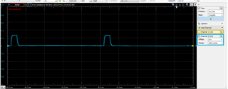
Iam trying to follow the application report slaae25. Sometimes I get  a PPG signal on the GUI and sometimes there is no signal. 

Firstly I thought it was because of the LED and PHOTO diode assembly as it was quite unstable. So then I shifted to a Medical Grade SPO2 finger clip.

but the results are still same.

Help me where I'am going wrong?


How do I get a more Stable system ? 

Thanks.

  • Hi iqra shaikh,

    Without knowing much about your system it will be difficult to determine exactly where the problem is. If you have access to a scope, try to determine if there is any instability in the photodiode/LED HW by probing those signals. If not there this is probably a SW issue or connection issue between the MSP430 and the PC.

    Please provide more details about what you are observing and what your HW setup is.

    Also, do you have an active CCS debug session when this is occurring? If so that may be an issue with the setup. Please click the red square to disconnect from the device.

    Regards,

    Evan

  • Hi Evan,

    I'am following TIs application note. The Link is https://www.ti.com/lit/an/slaae25/slaae25.pdf?ts=1650270665071&ref_url=https%253A%252F%252Fwww.google.com%252F

    This is what my system looks like.

        This is the block diagram of the system. 

    I 'am probing the oscilloscope at to current setting Resistor of RED LED and at the cathode of the photodiode.

    I'm using the GUI provide by TI with the application note to view the PPG signal.

    This is the oscilloscope View and the corresponding PPG signal.

    Sometimes I get a very clear signal on the GUI and sometimes the signal is too distorted or just noise. 

    The Application note is followed as it is. As you suggested it might be communication issue with MSP430 and PC, it can be a possibility. But even when I am not using communication between PC and controller and simply trying to compute SPO2 and Heart Rate the Computed results are neither consistent nor correct.

    Can it be possible that the jumpers that I 'am  using to connect the Probe with the System are introducing noise ?  

  • Thanks for the detailed follow up. However, based on the screenshots and data you have provided it's not clear which part of the system is involved in the issue. For example: when you see a bad signal in the GUI do you see any changes in the signals on the scope? I would recommend performing some tests that will help isolate the root cause of the issue, otherwise it will be too difficult to find where the problem is.

    Can it be possible that the jumpers that I 'am  using to connect the Probe with the System are introducing noise ?

    It's a possibility. If you move the wires does it introduce any visible noise?

    Regards,

    Evan

  • Irrespective of the  signal displayed on the GUI. The signals on the Oscilloscope remains similar. I cannot read the exact voltage levels because its a function of time. But the waveform looks similar every time.

    It's a possibility. If you move the wires does it introduce any visible noise?

    Yeah moving the wires also change the visible PPG signal. 

    I'll get a more stable connection solution for the probe first, to see if the issue is resolved.

    And I also had some doubts with the code.

    The Ratios of Ratio is give by this Relation. Is there a need to change this relation for every system ? 

    Thanks,

    S. Iqra.

  • Hi S. Iqra,

    If the scope output is stable but the GUI is not then I suspect the issue is somewhere between the PC and the MPS430. Can you confirm: you are not using the debugger when this issue is happening?

    Can you clarify you question about the code? Also, where did you download this code? I can't find a function called calculated_spo2 in the TI provided code.

    Regards,

    Evan

  • Hi Evan,

    I tried taking multiple readings for both cases.

        1. while the debugger is on.

        2. while the debugger is off.

    And I can observe output variations in both cases.

    I can even observe something strange on the readings on the oscilloscope.

    The waveform used to drive the LED. ( Its set to 500mV in the code by me).

    But for some readings it has a different value and for others it has some other value.

    LED Driving Waveform. 


    Observed Voltage levels.

    70mV

    300mV

    150mV 

     Although the PPG wave was independent of this variation as well.   

    Can you clarify you question about the code? Also, where did you download this code? I can't find a function called calculated_spo2 in the TI provided code.

    I extracted the code from the zip-file provide in the application note.

     Its a function in algorithm.c  file.  

    Thanks,

    S. Iqra 

  • Thanks for the detailed response. 

    I'm not surprised that some of the LED driving waveforms are different from each other. If you read section 5.1 of the guide there are provisions for the LED drive strength to be modulated.

    We still have not determined any correlation between signals we are observing on the HW and the "bad" GUI readings which is making it difficult to determine where we need to focus our debug efforts. Do you have any thoughts on what configurations are causing "bad" readings? Is the setup changing at all? Is the finger clip always clips to the same finger in the same way? 

    If you have any other thoughts on how to isolate the problem please give those a try.

    Regards,

    Evan

  • Hi Evan,

    The section 5.1 of the Application Note does mention that there is feedback present which controls the LED driving current.  But if I look into the code provided by TI I find no such feedback present in the code. There is only one place where the LED current is set and it has to be changed manually.

     I cannot find any other instance where the led levels are changed.

    Can you please help me with an approach to debug this issue.

    Thanks,

    S. Iqra

  • Hi Igra Shaikh,

    You are right, I don't see any code to automatically update the LED drive strength. I'm guessing since it may depend on LED/photodiode device selection that code is left to the user to implement. I'll check with my team about that.

    We still have not found the root cause of the instability. I would suggest checking all parts of the LED driver hardware. First, if you measure the voltage at R5 and R6 is it 500mV as expected?

    Evan

**Attention** This is a public forum