This thread has been locked.

If you have a related question, please click the "Ask a related question" button in the top right corner. The newly created question will be automatically linked to this question.

MSP430FR50431: MSP430FR50431

Part Number: MSP430FR50431
Other Parts Discussed in Thread: EVM430-FR6043, EVM430-FR6047, , MSP430FR6043

Hi
I try to send our schamatic for rviewe to : msp-sbd-review@list.ti.com
I get an unswer that the mail an not available.
Please halp me to forword our Shcmatic for review.

Avraham

Clip ON MSP430FR50431 100123.pdf

  • Hi Avraham,

    I mistakenly told you to send it to this list. In the future, you should inquire about schematic reviews with your TI sales representative.

    However I will still leave some notes for you as you should not be inconvenienced by my mistake.

    I see you've highlighted the UART TXD and RXD. These look correct and it looks like they are connected to the JTAG header correctly as well. I also see that you've highlighted the resistors connected to pins 2 and 4 of the JTAG header. In our reference design, these do not have the zero ohm resistors, but these should not cause problems. One thing I notice is that you do not have a button or anything to pull your reset signal low in the event that you'd like to manually reset the device. You also want to have this pulled high by default instead of leaving it floating so that you do not experience erroneous resets of the device. You can find a description of the proper set up on table 7-4 of the datasheet, or you can consider the set-up in the reference design. Your crystals all look good. I see the passive components connected to CH0 and CH1 in and out are good, but I do not see the analog front end connections. I assume you are handling this on your own, but if you do have questions regarding this I would suggest that you look at the reference design. Looking further, this is true for many of the signals connected to the AFE (TxPwr, RxPwr, etc). Most of your bypass and decoupling caps look good, but I see you've opted to place resistors instead of inductors where you have R204, R205, and R206. You also use caps slightly different from what we recommend in section 10.1.1 of our datasheet. In the end, it is up to you to determine the hardware that gives you the best results, however you should be aware that these are different than what we recommend in the datasheet.

    In general, this looks good. For further questions I would encourage you to visit our reference design at this link, and post a thread here on E2E if you have confusion. Also please remember that it is up to you to perform the schematic's final evaluation.

  • Hi
    Thanks for your halpfull inputs.
    I can see some differnce between Both EVM and the data sheet.


    1: AFE signals:

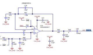
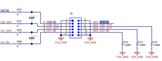
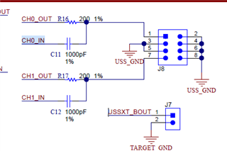
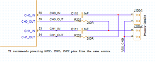
    In the EVM430-FR6043 I can see an analog comparator on the CH0 in, and 1M to GND on the CH0_OUT, CH1_OUT, CH1_IN.

    In the EVM430-FR6047

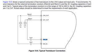
    In the datasheet Figure 10-6

    I have connect these signals acordind to the data sheet and EVM430-FR6047 do you see a problem with our implumantation? 


    2: PVCC decupling capacitor
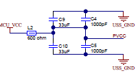
    On the Data Sheet PVCC are connected through 22ohm res and the decupling capacitors are 22u and 1nF.


    On both EVM I can see instead of the 22ohm an inductor

    What is your recomendation?

    3: HFXOUT crystal
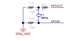
    In the EVM430-FR6047 it seemes like the crystal is not connected.

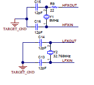
    In the EVM430-FR6043 it is connected.

    Do I need to assemly that Crystal?

    4: HFXOUT crystal internul capacitor
    On the bom description the internul capacitor shell be 9pF.
    Acordind to the PN that has been aseemly on the EVM : 8 MHz ±20ppm Crystal 18pF 140 Ohms


  • Hi Avraham,

    1) I see what you mean. Personally, I have only used the hardware set-up in the form of the EVM. I believe most customers perform their initial evaluation using the EVM as well. Using the configuration in the datasheet is not necessarily wrong, you are just using a set-up that I am less familiar with and you will be missing out on the benefits of the OpAmp driving your transducer signals. If this is OK in your application, then you can move forward according to the recommendations to the datasheet as you have done so far.

    2) I am seeing a pattern of the EVM differing a bit from the datasheet. As I mentioned with the previous question, I am more familiar with the EVM's configuration and since I have been using that configuration in all of my testing, I would suggest that you use the EVM as your first reference for your design, then the datasheet as your secondary. 

    3) The MSP430FR6043 and the MSP430FR50431 are the same, aside from the UART/I2C bootloader difference, and the presence of the LCD primarily. When in doubt, you should refer to the 6043 EVM for references.

    4) I am not seeing where the BOM specifies Y1 - HFXT, as 9pF. I see immediately below that the LFXT is specified to be 9pF, and the listed part is 9pF. Could you point me to where it says 9pF for the HFXT? In your screenshot I do not see a capacitance specification.

    Reading over these, I realize that the EVM differs from our datasheet in a few places. Considering that the EVMs were developed after the part itself, and they have undergone more application specific testing, I would say that you should value the EVMs as a reference higher than the datasheet. If there is some huge discrepancy or something that is worrying, feel free to point this out so I may take a closer look, but the EVM has been used successfully for a long time, and is also the only hardware on which I have used the part, so I consider it to be a very reliable aid when designing hardware. 

**Attention** This is a public forum