This thread has been locked.

If you have a related question, please click the "Ask a related question" button in the top right corner. The newly created question will be automatically linked to this question.

MSP430FR2476: Interrupt Vector Table issue in BSL Code

Part Number: MSP430FR2476
Other Parts Discussed in Thread: MSPBSL, MSP430FR2311,

Hi Team,

I am working on BSL code and able to flash the code correctly on the same location of the memory(0x8004).But I have two applications and both the applications uses WDT so when running two applications it is problem.

Application1 is flashed at location 0x8004 and Application2 is flashed at location 0x81BE.
Also tried coding with dualimage example of MSP430FRBoot – Main Memory Bootloader and Over-the-Air Updates for MSP430Tm FRAM Large Memory Model Devices. No use as both the generated linker file has single vector table.Also dual image is not neccessary for my application

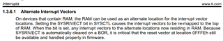
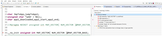
The starting application address for both app is same i.e. 0x8004 so for app2 i changed initial address to 0x81BE in this i also have to change the vector table.I wanted to know how can i add the vector table for app2.

Workflow of the my application is Boot code runs in the beginning and app1 is received through UART it is verified and runs. Now update the code i.e. application2 for this an interrupt in app1 moves from app1 to boot code and starts accepting app2 now in this process if issues occurs i need the program to jump to app1.


Regards,
Pallavi

  • Hey Pallavi,

    I don't fully understand the issue, as the vector table for the device is at a fixed address.  It seems you are trying to implement a main memory BSL, is that correct?  There is a ton of information on the MSPBSL page and it will link you to the MSP430FRBoot main memory BSL example which sounds similar to what you are trying to do.  

    Is that the OTA update example you mentioned?  

    Thanks,

    JD

  • Hi Crutchfield,
    Sorry for not explaining the issue properly.
    I am working on the BSL code by referring MSP430Tm FRAM Devices Bootloader (BSL) and OTA update from the example mentioned in MSP430FRBoot – Main Memory Bootloader and Over-the-Air Updates for MSP430Tm FRAM Large Memory Model Devices. 
    Host : MSP430FR2311

    Target : MSP430FR2476
    App1 : blink P1.0 LED of MSP430FR2476 using WDT

    App2: blink P4.7 LED of MSP430FR2476 using WDT

    Workflow:

    Host sends the App1 with the starting address of the app 0x8004 

    Target running the boot code receives the app1 process it and verifies and jumps to location 0x8004.while app1 is running P2.3 port interrupt disables all the interrupts and jumps back to boot code starting location.

    Now i have to send app2 (without overwriting app1).Keep running target in boot code and add app2 code in host and connect to PC.

    Host will send the app2 with the starting address of the app 0x81BE,target receives and processes it and jumps to 0x81BE location.

    Here app2 has entered and it contains on and off LED but WDT is not getting invoked because the #pragma vector = WDT_VECTOR is pointing to app1 P1.0 LED. So the WDT to blink P4.7 is not working.
    Based on this observation here we need two vector table, one table for app1 P1.0LED and another vector table for P4.7

    Below is the reference of all the files.As we are experimenting only the required part of code is added in both HOST and Target

    3223.BSL.zip

    Regards,

    Pallavi 

  • Hey Pallavi,

    Okay, so you are trying to manage two separate firmware images on the device, and have the ability to switch back and forth between them, correct?  We currently refer to what you are trying to write as a "Boot Image Manager" or BIM.  We have some BIM examples for our wireless devices and for MSPM0, but I am not aware of any for MSP430.  I'm not fully sure how they work, but maybe their documentation and the code can help you see how they implement this functionality.  

    Here is the MSPM0 BIM User's Guide: https://software-dl.ti.com/msp430/esd/MSPM0-SDK/1_20_00_05/docs/english/middleware/boot_manager/doc_guide/doc_guide-srcs/index.html# 

    And Here are the BIM Examples with the BIM application itself and a sample firmware image you can load: https://dev.ti.com/tirex/explore/node?node=A__AG-cEnMMa1GfTvRDf4FAuA__MSPM0-SDK__a3PaaoK__LATEST 

    Thanks,

    JD

  • Hey Pallavi,

    I spoke with a software engineer familiar with the MSPM0 BIM, and they are using a "vector table offset register" which is a new feature we do not have in MSP430.  

    Basically, you are going to have to update the vector table depending on with firmware image you are wanting to run. The TRM covers Alternate Interrupt Vector tables and how it can be move to RAM.   With this, your BIM would somehow determine which image is the correct one, and set the vector table accordingly.   Then it can be updated later if a newer image is loaded, ect.  

    Hope this helps, 

    JD

  • Hi JD,

    Thank you reply.

    Okay, so you are trying to manage two separate firmware images on the device, and have the ability to switch back and forth between them, correct? 

    Yes.Because main application will be running. Back to bootloader code and  In-field firmware update process starts  and while this process is going on if some issue arises in-field working of our application should not stop so it should go back to the previous version(application1) and continue in that 

    Also i went through the documentation and found RAM Vector will be useful so started implementing it. I got errors in these.

    referring this thread https://e2e.ti.com/support/microcontrollers/msp-low-power-microcontrollers-group/msp430/f/msp-low-power-microcontroller-forum/399114/how-to-use-sysrivect-bit-in-register-sysctl


    since i have three seperate files i have created "vector_table.h" file in main file and application files.

    #ifndef VECTOR_TABLE_H_
    #define VECTOR_TABLE_H_

    extern void app1_WDT_ISR();
    extern void app2_WDT_ISR();


    #define RAM_MAX_ADRESS 0x1FFF
    #define MAP_VECTOR_BASE (RAM_MAX_ADRESS-1-RESET_VECTOR)
    #define NUM_VECTOR ( 1+( (RESET_VECTOR-RTC_VECTOR)>>1) )


    __interrupt void app1_WDT_ISR(void);
    __interrupt void app2_WDT_ISR(void);

    #endif /* VECTOR_TABLE_H_ */

    main.c

    #include "msp430.h"
    #include "TI_MSPBoot_Common.h"
    #include "TI_MSPBoot_CI.h"
    #include "TI_MSPBoot_MI.h"
    #include "TI_MSPBoot_AppMgr.h"
    #include "vector_table.h"


    // Local function prototypes


    void Software_Trim(); // Software Trim to get the best DCOFTRIM value
    #define MCLK_FREQ_MHZ 8 // MCLK = 8MHz

    static void clock_init(void);
    tBOOL TI_MSPBoot_AppMgr_AppisValid(void);


    char JmpToApp,jumpToApp2;
    unsigned char *addr = NULL;
    char app1_downloaded,app2_start,app2_end;

    //#pragma NOINIT unsigned int MAP_VECTOR[ NUM_VECTOR ]@MAP_VECTOR_BASE


    __no_init unsigned int MAP_VECTOR[ NUM_VECTOR ]@MAP_VECTOR_BASE;
    /******************************************************************************
    *
    * @brief Main function
    * - Initializes the MCU
    * - Selects whether to run application or bootloader
    * - If bootloader:
    * - Initializes the peripheral interface
    * - Waits for a command
    * - Sends the corresponding response
    * - If application:
    * - Jump to application
    *
    * @return none
    *****************************************************************************/
    void main_boot(void)
    {

    WDTCTL = WDTPW + WDTHOLD;


    PM5CTL0 &= ~LOCKLPM5;
    clock_init();
    __bis_SR_register(GIE);

    P4DIR |= BIT7;
    P4OUT |= BIT7;
    __delay_cycles(5000);
    P4OUT &= ~BIT7;


    MAP_VECTOR[(WDT_VECTOR - RTC_VECTOR) / 2] = app1_WDT_ISR;
    MAP_VECTOR[(WDT_VECTOR - RTC_VECTOR) / 2] = app2_WDT_ISR;

    SYSCTL |= SYSRIVECT;

    addr = (unsigned char*) 0x1804;
    JmpToApp = *addr;

    //if ((*JmpToApp) == 1)
    if (JmpToApp == 1)
    {
    __disable_interrupt();
    ((void (*)()) 0x8004)();
    }

    if(JmpToApp == 2)
    {
    //jumpToApp2 = 0;
    __disable_interrupt();
    ((void (*)()) 0x81BE)();
    }
    // Validate the application and jump if needed
    if (TI_MSPBoot_AppMgr_ValidateApp() == TRUE_t)
    {
    __no_operation();
    TI_MSPBoot_APPMGR_JUMPTOAPP();
    }


    TI_MSPBoot_CI_Init(); // Initialize the Communication Interface

    while (1)
    {

    // Poll PHY and Data Link interface for new packets
    TI_MSPBoot_CI_PHYDL_Poll();

    if (app1_downloaded == 1 && app2_start == 1 && app2_end == 0)
    {
    __disable_interrupt();
    ((void (*)()) 0x8004)();
    }


    // If a new packet is detected, process it
    if (TI_MSPBoot_CI_Process() == RET_JUMP_TO_APP)
    {

    // If Packet indicates a jump to App
    //*JmpToApp = 1;

    //JmpToApp = 1;

    if (app1_downloaded == 1)
    {
    addr = (unsigned char*) 0x1804;
    SYSCFG0 = FRWPPW | PFWP;
    *addr = 2;
    SYSCFG0 = FRWPPW | DFWP | PFWP;
    }
    else if (app1_downloaded != 1)
    {
    addr = (unsigned char*) 0x1804;
    SYSCFG0 = FRWPPW | PFWP;
    *addr = 1;
    SYSCFG0 = FRWPPW | DFWP | PFWP;
    }

    app1_downloaded = 1;
    TI_MSPBoot_AppMgr_JumpToApp();

    }


    #ifdef NDEBUG
    // Feed the dog every ~1000ms
    WATCHDOG_FEED();
    #endif
    }

    }


    Error:

    tried noint also but same error comes up. I don't know hat is MAP_Vector here

    Regards,

    Pallavi

  • Hey Pallavi,

    I may have sent you in the wrong direction.  I found this really good thread from a few years ago that is bringing up a lot of good points for people porting MSPBOOT.  Caleb highlights the point that in FRAM devices, it isn't really required to move the vector table since we can just write FRAM almost as easy as RAM.   https://e2e.ti.com/support/microcontrollers/msp-low-power-microcontrollers-group/msp430/f/msp-low-power-microcontroller-forum/592033/msp430fr2311-custom-bsl-mapping-proxy-interrupt-vector-table-in-msp430fr-issue 

    Take a look through that thread and the linked thread to see if Caleb's insights help you get this working.  

    Thanks,

    JD


  • Hi JD,

    I have the following thread and understood that proxy vector table or the RAM Vector is required for FR model.

    Changed the linker file of WDT

    SECTIONS
    {
    .bss : {} > RAM /* GLOBAL & STATIC VARS */
    .data : {} > RAM /* GLOBAL & STATIC VARS */
    .sysmem : {} > RAM /* DYNAMIC MEMORY ALLOCATION AREA */
    .stack : {} > RAM (HIGH) /* SOFTWARE SYSTEM STACK */

    .text:_isr : {} > FLASH /* Code ISRs */
    #ifndef __LARGE_DATA_MODEL__
    .text : {} >> FLASH /* CODE */
    #else
    .text : {} >> FLASH | FLASH2 /* CODE */
    #endif
    .cinit : {} > FLASH /* INITIALIZATION TABLES*/
    #ifndef __LARGE_DATA_MODEL__
    .const : {} >> FLASH /* CONSTANT DATA */
    #else
    .const : {} >> FLASH2 | FLASH /* CONSTANT DATA */
    #endif

    .cio : {} > RAM /* C I/O BUFFER */

    /* MSP430 INTERRUPT VECTORS */
    .int00 : {} > INT00
    .int01 : {} > INT01
    .int02 : {} > INT02
    .int03 : {} > INT03
    .int04 : {} > INT04
    .int05 : {} > INT05
    .int06 : {} > INT06
    .int07 : {} > INT07
    .int08 : {} > INT08
    .int09 : {} > INT09
    .int10 : {} > INT10
    .int11 : {} > INT11
    .int12 : {} > INT12
    .int13 : {} > INT13
    .int14 : {} > INT14
    .int15 : {} > INT15
    .int16 : {} > INT16
    .int17 : {} > INT17
    .int18 : {} > INT18
    .int19 : {} > INT19
    ECOMP0 : { * ( .int20 ) } > INT20 type = VECT_INIT
    PORT6 : { * ( .int21 ) } > INT21 type = VECT_INIT
    PORT5 : { * ( .int22 ) } > INT22 type = VECT_INIT
    PORT4 : { * ( .int23 ) } > INT23 type = VECT_INIT
    PORT3 : { * ( .int24 ) } > INT24 type = VECT_INIT
    PORT2 : { * ( .int25 ) } > INT25 type = VECT_INIT
    PORT1 : { * ( .int26 ) } > INT26 type = VECT_INIT
    ADC : { * ( .int27 ) } > INT27 type = VECT_INIT
    EUSCI_B1 : { * ( .int28 ) } > INT28 type = VECT_INIT
    EUSCI_B0 : { * ( .int29 ) } > INT29 type = VECT_INIT
    EUSCI_A1 : { * ( .int30 ) } > INT30 type = VECT_INIT
    EUSCI_A0 : { * ( .int31 ) } > INT31 type = VECT_INIT
    //WDT : { * ( .int32 ) } > INT32 type = VECT_INIT

    WDT : {} > 0xF400 type = VECT_INIT                                //CHANGED HERE

    RTC : { * ( .int33 ) } > INT33 type = VECT_INIT
    TIMER0_B1 : { * ( .int34 ) } > INT34 type = VECT_INIT
    TIMER0_B0 : { * ( .int35 ) } > INT35 type = VECT_INIT
    TIMER3_A1 : { * ( .int36 ) } > INT36 type = VECT_INIT
    TIMER3_A0 : { * ( .int37 ) } > INT37 type = VECT_INIT
    TIMER2_A1 : { * ( .int38 ) } > INT38 type = VECT_INIT
    TIMER2_A0 : { * ( .int39 ) } > INT39 type = VECT_INIT
    TIMER1_A1 : { * ( .int40 ) } > INT40 type = VECT_INIT
    TIMER1_A0 : { * ( .int41 ) } > INT41 type = VECT_INIT
    TIMER0_A1 : { * ( .int42 ) } > INT42 type = VECT_INIT
    TIMER0_A0 : { * ( .int43 ) } > INT43 type = VECT_INIT
    UNMI : { * ( .int44 ) } > INT44 type = VECT_INIT
    SYSNMI : { * ( .int45 ) } > INT45 type = VECT_INIT

    .reset : {} > RESET /* MSP430 RESET VECTOR */
    }

    But LED Flash doesnot works.If my understanding is wrong can you tell me which location i have to edit 
    This is app1.c

    #include "msp430.h"
    #include <stdint.h>
    #include "TI_MSPBoot_Mgr_Vectors.h"


    int main()
    {

    WDTCTL = WDT_ADLY_1000; //Every 1 second watchdog gets invoked
    SFRIE1 |= WDTIE;

    // Toggle LED1 in P1.0
    P1DIR |= BIT0;
    P1OUT |= BIT0;
    PM5CTL0 &= ~LOCKLPM5;
    __delay_cycles(500000);
    P1OUT &= ~BIT0;
    __delay_cycles(500000);
    P1OUT |= BIT0;
    __delay_cycles(500000);
    P1OUT &= ~BIT0;

    P4DIR |= BIT7;

    // Start P2.3 (S2 button) as interrupt with pull-up
    P2DIR &= ~BIT3;
    P2REN |= BIT3;
    P2IES |= BIT3;
    P2IFG &= ~BIT3;
    P2IE |= BIT3;

    __bis_SR_register(GIE);

    while(1)
    {
    __no_operation();
    }

    // return 0;
    }

    #pragma vector = WDT_VECTOR
    __interrupt void app2_WDT_ISR(void)
    {
    P4OUT ^= BIT7;
    }


    #pragma vector = PORT2_VECTOR
    __interrupt void Port2_Isr(void)
    {
    P2IFG = 0;
    TI_MSPBoot_JumpToBoot();
    }


    i think i have to change WDT_VECTOR location. currently it is pointing to 0xFFE2

**Attention** This is a public forum