This thread has been locked.

If you have a related question, please click the "Ask a related question" button in the top right corner. The newly created question will be automatically linked to this question.

MSP430FR6047: Water meter cycle slips

Part Number: MSP430FR6047

Hello,

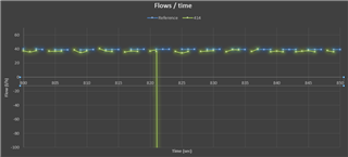
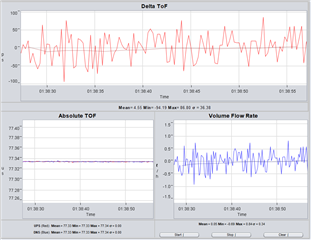
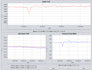
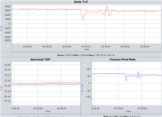
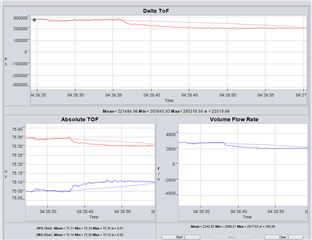
I am building a water meter solution for my company and now I am at the stage where I am trying to calibrate the devices. I did what was proposed in this thread (Cycle slipping solution) (set  USS_ALG_MAX_RATIO_PEAK_2_PEAK_VAR  to 0). But I still get a few cycle slips. What I find the most odd is that when the flow increases (between 6 -> 100 l/h), cycle slips also increase. For example when flow increases, from 7770 measurements, across three devices, 123 of these measurements display abnormal values, either positive (~5000 l/h) or negative (~ -2500 l/h), and most if not all appear from 6 to around 50 l/h. When flow decreases, from 15243 measurements only 7 were abnormal. Temperature was also varied from 10 to 40 degrees Celsius but I didn't find any correlation through this. Note that the increase/decrease isn't direct from 6 to 100. It passes through a lot of flows. It may get hundreds of measurements from one flowrate.

What should I do further to eliminate cycle slips?

Is there any more information that you would like to know about my solution?

I saw in this thread that it would be good to reduce signal sampling frequency to 3600 and set USS_ALG_DTOF_WINDOWING_MODE to USS_ALG_DTOF_EST_WINDOW_OPTION_DISABLED. Would these settings help?

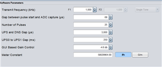
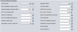
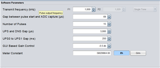
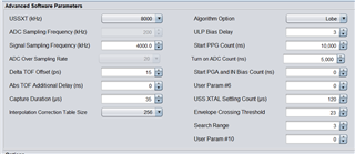
This is the configuration that I use

  • Hi,

    Could you provide some ADC captures here? And also the waveform data with the cycle slip issue you observed. 

    Best regards,

    Cash Hao

  • Hello Cash,

    Sorry for the late reply. I was out of office

    Here is an ADC capture

    Here is a snippet from a waveform where the cycle slip occurred


    The blue points are the flow measured from our reference device and the green from the device we are trying to calibrate. The value measured at the cycle slip is ~-5000l/h, but the graph would show correctly if the y axis went to this value.

    Measurements are taken every 250ms and every four measurements are combined into an average, so every second I get a reported l/h value which is shown in the graph above

    Also I have another question. We are using a custom board and I have the EVM to configure the parameters.

    After I finish with the configuration of the EVM, I pass the configuration settings to the custom MSP30FR6047 board which has the same pipe, same type of transducer (same MHz, same manufacturer company) and same transducer distance. Except of the meter constant and the VFR Flow and temperature calibration, is there anything else that needs to be changed to get accurate measurements?

    For example should I do frequency sweep for every device or should I keep the same frequency that I found on the EVM since all of them use the same type of transducer?

  • Hi,

    For the cycle slip issue, I could not tell if this issue is caused by the cycle slip on the absTOF result or only on the dTOF result. So, I would suggest to use less excitation pulses, like 12 to 16 and test again. 

    Usually you can keep the same frequency and same other parameters for mass production. However, it depends on your accuracy requirement. If you target at measuring below 10LPH, you may need to tune each parameter suitable for each meter to achieve this kind of requirement. 

    Best regards,

    Cash Hao

  • Hello,

    Here are the new configurations

    Are they good? Should I change anything before I continue with the testing?

  • I may have been wrong with the value of the gap between pulse start and adc capture. I measured the distance of the transducers at 8cm, so the value should be 44 by using this equation (ADC Start Capture Time = (Ultrasonic Path Length/Speed of Sound) – 10us) and not 69 that I have been using?

  • Hi,

    These parameters looks good to me. Please continue testing with these parameters again. 

    Your ADC start capture time as 69 looks good to me. It can capture the full receive signal showed in the ADC capture. So, no need to change it to 44. 

    Best regards,

    Cash Hao

  • Hello Cash,

    I have taken a little more than 14000 measurements across 2 devices. Only one time I have gotten a wrong value. -33 lph when it should be around 30 lph. All the others were correct.

    The new configuration is a big improvement compared to the previous one.

  • Hello Cash,

    But the issue still persists, albeit in a smaller factor. Is there anything else that we can do, to eliminate this entirely?

  • Hi,

    Only one wrong value at -33LPH, I think it is mostly caused by some noise. These parameters still looks good, and it does not looks like a cycle slip issue happens. Because a cycle slip will cause a much bigger difference to the VFR. So, my guess is some noise affect that measurement. 

    Best regards,

    Cash Hao

  • The value -33lph is an average of 4 measurements made at 250ms intervals, so the wrong value could be at around -200lph, if one of these four measurements were wrong

  • Hi,

    Unless you have the exact absTOF and dTOF data when this error point happens. If so, we can know what is causing this wrong point. 

    Best regards,

    Cash Hao

  • I will take some new measurements to gather absTOF and dTOF data when I have a wrong measurement and I will send them

  • Okay. Wait for your result.

  • Hello Cash,

    I took ~15000 measurements across 3 devices

    I have attached a drive link to the excel showing all the wrong measurements I took when 6 to 100 vfr was flowing through the devices (every measurement above 150 and below -5 vfr) 

    docs.google.com/.../edit

  • Hi,

    I checked these data. I do not find cycle slip issue on both dTOF and absTOF result. 

    Use expected flow rate at 30 for example. 

    expected flow dtof tof_ups tof_dns uncalibrated vfr (measured flow)
    30 -5.39E-10 7.49E-05 7.49E-05 -5.577560425
    30 5.15E-08 7.49E-05 7.49E-05 532.5809326
    30 3.87E-08 7.54E-05 7.53E-05 395.8002014
    30 -1.27E-09 7.53E-05 7.53E-05 -12.95262146

    The dTOF varies from -1.27ns to 51.5ns. The absTOF_ups varies from 74.9us to 75.4us.  The absTOF_dns varies from 74.9us to 75.3us.  These variation is below 1 transducer period, so it is not cycle slip issue. Not an issue caused by the software. 

    But still, around 53ns variation on dTOF and around 0.5us absTOF are abnormal behavior. I would consider that there is some noise goes into ADC capture and causes this error. Maybe there are bubbles in the pipe. 

    Have you seen this kind of error at higher flow rate? How many measurements do you take when you change to a new flow rate? Does these errors usually happens on the first half of the total measurements at this flow rate. 

    Best regards,

    Cash Hao

  • Have you seen this kind of error at higher flow rate?

    I haven't tested yet with higher flow rates. I will do it and report

    How many measurements do you take when you change to a new flow rate?

    I take around 192 measurements before I change to the next flow. 48 seconds of measurements


    Does these errors usually happens on the first half of the total measurements at this flow rate. 

     80% of them happen during the transition of the flow (going from 30 -> 35 or 30 ->25 lph) (the max flow change is 5 lph), the others near at the start where the flow has stabilized 

    Also I would like to note that the 4 measurements you showed above belong to 2 different devices. The first two are from one device and the other two are from another

  • I connected the evaluation board and tried different flows

    On higher flows it looks more stable

    60->70 vfr

    70->60

    2800->2000

  • Hi,

    I would consider there is bubbles in the pipe based on these data, especially at lower flow rate. 

    I would recommend before you start your test, run your test bench at highest flow rate like 2800LPH for one minute. It could help to bring the bubbles out of the pipe. And then you test something like 2800->2000->1600->1000->600->... and on.

    And the dTOF data can have some turbulence when you change the flow rate. It is quite normal.  

    Best regards,

    Cash Hao

  • I would recommend before you start your test, run your test bench at highest flow rate like 2800LPH for one minute.

    I already do that

    And the dTOF data can have some turbulence when you change the flow rate.

    So it's normal to have so high deviations sometimes?

  • Hi,

    Yes, I will consider it normal during flow rate changing. 

    Best regards,

    Cash Hao

  • Hello Cash,

    Great. Thank you for your help!!!!!

**Attention** This is a public forum