This thread has been locked.

If you have a related question, please click the "Ask a related question" button in the top right corner. The newly created question will be automatically linked to this question.

EVM430-FR6047: One transducer channel has large negative amplitude (even without transducer attached)?

Part Number: EVM430-FR6047
Other Parts Discussed in Thread: MSP430FR6047

Tool/software:

Everything was working (minus the LCD). Flow measurements were looking good. I swapped out the transducers with transducers of similar capacitance and got an "unknown error". I posted a question and the community helped me get it re flashed and it was working like new again, but today regardless of the transducer configuration it says "No signal detected in up and downstream channel". I tried reflashing and adjusting settings, but no change.

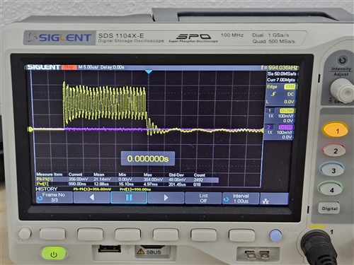
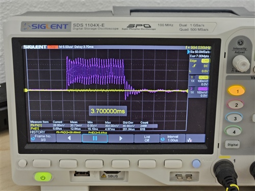
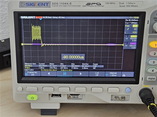
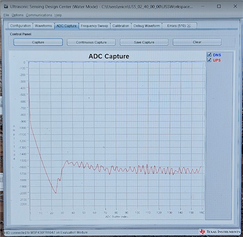
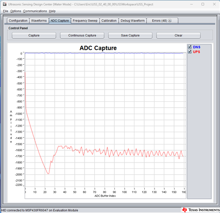
More upsetting is that the ADC capture shows a very negative upstream channel (not the normal noise near zero). This persists regardless of if flow meter transducers are connected or not. I am worried this is permanent board/chip damage.

This has occurred on 2 of 2 eval boards. The second one I made certain there was never a short circuit and it instantly went in the the "unknown error" issue.

  1. Any idea what "unknown error" could encompass? and why re flashing it makes it go away?
  2. Any idea what would make that upstream channel go low like that?
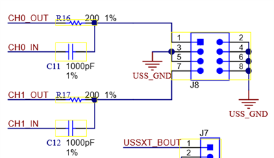
  3. It looks like the output is current limited with a resistor and the input blocks DC with a capacitor. Should there be additional protection on these? Like TVS diodes?
  4. Even speculation would help, I am stumped. All I can figure is the previous transducers had some sort of TVS or electrostatic protection build in?

  • Hi,

    Use an oscilloscope to check the signal of UPS and DNS. Check whether there is any difference between the UPS and DNS signal first. It could tell us if it is a hardware issue or an issue related to the MCU.

    You can put the probe on J8-1 and J8-7.

    Best regards,

    Cash Hao

  • Hi Cash,

    Thanks for having a look, I appreciate it!

    The yellow channel was hooked to CH1 J8-7 and the purple channel was hooked to CH0 J8-1. The transducers/flowmeter I am using are audiowell brand on a custom flowmeter. This flowmeter worked well on the eval board before the damage from the other transducers. Again note that this is not the firmware the device shipped with. I flashed Windows Installer for USS Water Demo for FR604x to it with code composer studio.

    Three different history captures.

    1. Transducers attached, empty flow meter (air).
    2. Transducers attached, flooded and fluid flowing.
    3. Transducers disconnected.

    1. Transducers attached, empty flow meter (air).

    2. Transducers attached, flooded and fluid flowing. You can see the received signal on the other channel on the right side.

    3. And with transducers disconnected.

    In all 3 scenarios the ADC Capture in the gui looks like this with just slight change in the transient noise at the beginning.

    Adding the XML as code blew up this editor, so here is a photo of it. Mostly default settings, but note that the gapBetweenPulseAndCapture is large because I have large spacing between transducers.


  • Hi,

    The oscilloscope pictures look good to me.

    I am thinking there is damage inside the MCU at this point. I would suggest you to apply some MSP430FR6047 samples and replace the one on the EVM board. 

    One question, you number of pulses setting is 50. First, we usually set this parameter below 25 pulses. Second, however in your picture, there is only 25 excitation pulses showed in the graph. I am confused in this setting. 

    Best regards,

    Cash Hao 

  • I was switching between computers, this probably wasn't the flashed profile. I will experiment with that value. I ordered the zif board and 10 new processors to get back up and running.

    The problem is that I don't know how I damaged it or how to address this going forward. All I can think is ESD or over voltage from the transducers. Other possibilities? Thoughts on adding TVS diodes?

  • Hi,

    The ESD is one possible cause. And since you are using 50 number of pulses, if your transducer's impedance is quite small, it could also bring in over current issue. 

    I would not suggest to add other components on the ultrasonic signal side. It will lower the performance.  

    Best regards,

    Cash Hao

  • It seems like the driver is okay though per the oscilloscope tests, so probably not over current right?

    It seems some portion of the input has died. Would setting the PGA gain lower on the new chips reduce the risk of damage? Are there clamping or TVS diodes after the PGA?


    I will use better ESD procedures on these new ones, but I am not confident it will solve the issue since I had no issues with the other transducers for months.

    Maybe the other transducers had lower quality PZT ceramic with more internal losses that masked the issue.

    Still brainstorming; if you have any ideas please throw them out. Thanks!

  • Hi,

    Yes, I agree that this issue is related to the input path. But I do not think this issue is related to ADC. Because the DNS signal can be captured without error. So, I am thinking some where before the PGA is damaged. I think lower the excitation pulses should still be helpful to avoid this issue. 

    Best regards,

    Cash Hao 

  • Cash, I replaced the processor on the damaged evaluation board and it works like new. Still not sure why this happened, but this at least tells us that it was not an issue with the capacitors on the inputs. I know you don't recommend components on the ultrasonic side, but I am 0 in 2 on these evaluation boards. I will add this D3V3Z1BD2CSP-7 TVS diode to the transducer connections before testing the new transducers again. I will report back if that solved it or not.


  • Hi,

    Okay. Please update your test result with the TVS diode when you done it. Thanks.

    Best regards,

    Cash Hao

**Attention** This is a public forum