MSP-EXP430F5529LP: Regarding designing of MSP-EXP430F5529LP

Part Number: MSP-EXP430F5529LP
Other Parts Discussed in Thread: MSP-GANG, MSP-FET, BQ40Z80, EV2400

Tool/software:

Dear Sir,

We are thinking of using your above mentioned MSP controller for designing of our new design. I have few doubt regarding it, please help me in clarification of it. I have mentioned below my doubts:

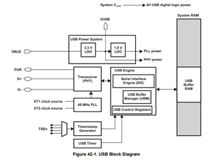
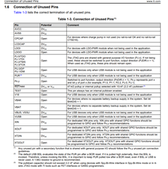
1) Related to USB pin of MSP controller:


I am confused about this pin. This pin is used for what purpose? This pin is used for  external usb detection when external usb is connected?


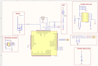
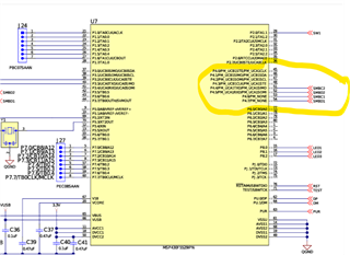
2) Related to external JTAG interface:

I am confused about, I want to provide connection for external programmer to program our MSP-controller. Which pin i should used. Actually, in datasheet it is given information about 6 pin about JTAG interface. But through datasheet, I have found out 4 pin. Please, help me out is there any Hardware design document related to it.


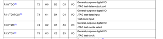
3) Related to IC supply current:

There is nothing mentioned about operating current of IC i.e Icc. Can you please help me out to find out what is operating current of Ic.

Waiting for your reply,

Regards,
Shubham

  • Hi Shubham,

    1. VBUS is an input from the USB for power. MSP430F5529 User's Guide

    2. For programming you can use either the 4-wire JTAG connection or 2-Wire Spy-Bi-Wire (SBW). Details and diagrams can be found in this document - MSP430 Hardware Tools User's Guide
    3. Current will vary depending on what you're doing in the application. For the CPU current, the Active mode and Low-power modes are relevant. Otherwise in the peripheral's specifications, the needed currents will be listed. MSP430F5529 Datasheet

    Recommended Document - Starting a USB Design Using MSP430

    Regards,
    Luke

  • Dear Sir,

    Is there any MSP JTAG programmer available which can be used to program our MSP controller externally, actually MSP-430GANG which is mentioned in JTAG programmer HW user guide, is out of stock. Can you mention any alternate cheap option.

    Also sir, what to do with the unused pins of MSP430F controller it should be left floating or not connected?

    Waiting for your reply,

    Regards,
    Shubham

  • Hi Shubham,

    You can program with the MSP-FET but this would be for single chip programming, whereas the MSP-GANG is for production programming. Here is a list of a couple companies that have multi-programming support (these are not endorsed)

    • Softlog (ICP2-GANG, ICP2-COMBO)
    • Phyton (CPI2-Gx)
    • Xeltek (SuperPro6104NGP)
    • DediProg (NuProgPlus-U8)
    • SMH (Flash Runner 2.0)

    For connection of unused pins, these are listed in the Family User's Guide

    Regards,
    Luke

  • Dear sir,

    I have designed my custom PCB board which contains MSP430F5529IPNR controller which serves as same purpose as it functions intended in BQ40Z80-EVM board. Means, I have connected my BQ40Z80 I2C lines to these controller i2c lines and also these i2c lines gets connected to my STM controller also which I am using for monitoring purpose respective pins as given in BQ40Z80-EVM module.Sir, I have designed the schematic I want you to please review my design and let me know if any flaws present in it. Also, as suggested by you I had made connection to unused pins of my MSP430F5529IPNR.
                   .
    Also, sir I have also included a programming header in it so in future if we have to flash the controller we can use it.

    Waiting for your response,

    Regards
    Shubham

  • Hi Shubham,

    I'll review the schematic tomorrow, is there a way you can attach it as a .jpeg or .png? The image is a bit blurry going through text box.

    Regards,
    Luke

  • Dear Sir,

    Please find the a pdf of my MSP controller schematic section, Please review it and let me know if any flaws are present. Also, please verify whether unused pins are properly terminated or not.

    5857.Sheet1.pdf

    Waiting for your reply,
    Regards,
    Shubham

  • Hi Shubham,

    Looks good to me and looks like you've been following our MSP430 Hardware tool's user's guide and Starting a USB design using MSP430.

    I did notice no external capacitors for your HFXT, looking at the schematic symbol it looks like there are internal capacitors, but double check with the crystal datasheet that there are no extra load capacitors needed.

    Also on the schematic you sent there are no I2C pull-ups, make sure you have pull-ups in the system for I2C connection. Values of the pull-ups should also be chosen based on your intended I2C speed, with lower value resistors for faster speeds.

    Regards,
    Luke

  • Dear Sir,

    1) Related to pull up: Sir actually, my i2c signal is going to STM, which I have represented on another schematic sheet. Thats why I have used ports in my schematic. Moreover, the pull up resistors are 10k and I had implemented on STM controller sheet where these i2c signal is going & getting connected. Therefore, I thought of not including a pull-up resistor here as all the components will be on one single board only. My frequency of operation is 100khz.

    2) Related to load capacitors: I am using resonator in my design, which have internal load capacitors, so I think there is no requirement for external load capacitors. I have also attached the image of the resonators that I am using. Please take a look at it and let me know if it is proper.


    Sir, I also have one more doubt, and I want clarification from you. Actually, in BQ40Z80-EVM20 schematic, pins 53 and 54 are used as i2c, which means i2c signals are getting connected to that pin. But in datasheet of MSP430F5529IPNR controller, these pin function is just given GPIO with no secondary function.So, sir how they are using it as I2C? I have attached image below for your reference, Please have a look in to it,


    Waiting for your reply,

    Regards,
    Shubham

  • Hi Shubham,

    1. 10k for 100kHz is a good value, though I would recommend a MSP device instead of STM, if I get the part number I can help find an MSP alternative.
    2. I agree that crystal has the built in load caps so it shouldn't require any extra caps.

    The BQ40Z80-EVM20 was made by the battery gauge team so, I'll pass to them to answer that. But it is possible to bit-bang the I2C communication on GPIOs, though not preferred.

    Regards,
    Luke

  • Hi Shubham,

    The MSP system design on the bq40z80EVM is pulled from the EV2400, where there is an I2C and SMBus port for connection. On the EV2400, the SMBC1/SMBD1 is for SMBus and the SMBC2/SMBD2 is for I2C. I believe that when this board was designed, they wanted to change this system as little as possible, so they are just tied together since bq40z80 only uses SMBus:

    When designing your own system, I think it should be fine just having one set for just the SMBus connection.

    Regards,

    Anthony Baldino

**Attention** This is a public forum