This thread has been locked.

If you have a related question, please click the "Ask a related question" button in the top right corner. The newly created question will be automatically linked to this question.

Compiler/MSP430F5328: MSP430F5328 interface with W25X10 winbound serial flash using SPI

Part Number: MSP430F5328

Tool/software: TI C/C++ Compiler

Hi,

I am using MSP430F5328 interface with W25X10 winbound serial flash using SPI communication protocol. I am using SMCLK 16MHz.

I have configure SPI based on the slave device & source code as below:

#define SPICLK        32
uint8_t SourceAddr [16];    
uint8_t DestAddr[16];

void main( void )

uint16_t IDcode = 0;

        //Set P2.6 for slave reset
        GPIO_setAsOutputPin( GPIO_PORT_P2, GPIO_PIN6 );
        GPIO_setOutputHighOnPin( GPIO_PORT_P2, GPIO_PIN6 );              
        
        //P3.3,4 option select 
        //FLASH_SPISIMO - P3.3
        //FLASH_SPISOMI - P3.4
        GPIO_setAsPeripheralModuleFunctionInputPin( GPIO_PORT_P3, GPIO_PIN3 + GPIO_PIN4 );
        //P2.7 FLASH_SPICLK
        GPIO_setAsPeripheralModuleFunctionInputPin( GPIO_PORT_P2, GPIO_PIN7);
    
        //Initialize Master
        USCI_A_SPI_initMasterParam param = {0};
        param.selectClockSource = USCI_A_SPI_CLOCKSOURCE_SMCLK;
        param.clockSourceFrequency = UCS_getSMCLK();
        param.desiredSpiClock = SPICLK;
        param.msbFirst = USCI_A_SPI_MSB_FIRST;
        param.clockPhase = USCI_A_SPI_PHASE_DATA_CHANGED_ONFIRST_CAPTURED_ON_NEXT;
        param.clockPolarity = USCI_A_SPI_CLOCKPOLARITY_INACTIVITY_LOW;
        returnValue = USCI_A_SPI_initMaster(USCI_A0_BASE, &param);                

        if (STATUS_FAIL == returnValue)
                return 0;
        
        //Enable SPI module
        USCI_A_SPI_enable(USCI_A0_BASE);
        
        //Now with SPI signals initialized, reset slave
        GPIO_setOutputLowOnPin( GPIO_PORT_P2, GPIO_PIN6 );  

        /* Reading Manufacturer ID */

IDcode = SerialFlash_ReadID();

}

uint16_t SerialFlash_ReadID(void)
{
    uint16_t IDcode;


    // P2.6 -- 0, CS = 0 Select SPI Flash
    GPIO_setOutputLowOnPin(GPIO_PORT_P2, GPIO_PIN6);

          
    // Read device commands     0x90
    SourceAddr[0] = 0x90;    
    // The upper part of the device address 0x00
    SourceAddr[1] = 0x00;    
    // The lower part of the device address 0x00 
    SourceAddr[2] = 0x00;    
    SourceAddr[3] = 0x00;   
    // Serial Flash send data    
    SerialFlash_SendData ( (uint8_t *)&SourceAddr[0],  4 ); 
    __delay_cycles(160000);
    // Serial Flash Receive data
    SerialFlash_RcvData( (uint8_t *)&DestAddr[0], 2 );


    // P2.6 -- 1, CS = 1 Release the SPI Flash
    GPIO_setOutputHighOnPin(GPIO_PORT_P2, GPIO_PIN6);


    // Get the IDcode
    IDcode = (DestAddr[0] << 8)|(DestAddr[1]);


    return IDcode;         
}

void SerialFlash_SendData( uint8_t *buf, uint32_t Length )
{
  uint32_t i;      
  for ( i = 0; i < Length; i++ )
  {    
      // USCI_A0 TX buffer ready?
      while (!(UCA0IFG&UCTXIFG));     
      UCA0TXBUF = *buf;
      buf++;      
  }  
}

void SerialFlash_RcvData( uint8_t *buf, uint32_t Length )
{
    uint32_t i;   
    for ( i = 0; i < Length; i++ )
    {           
        // USCI_A0 RX buffer ready?
        while (!(UCA0IFG&UCRXIFG));
        *buf = USCI_A_SPI_receiveData(USCI_A0_BASE);
        buf++;
    } 
}

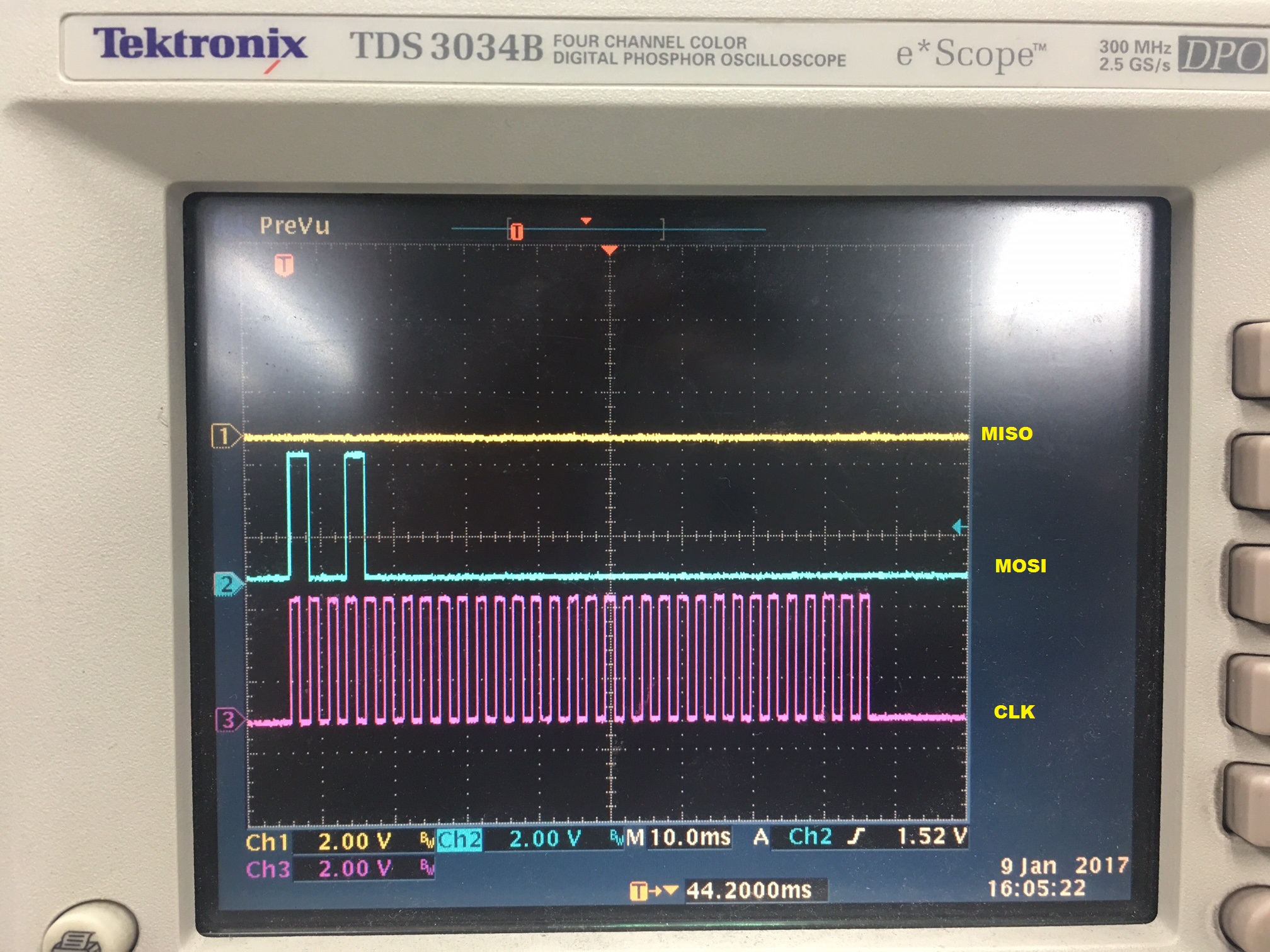
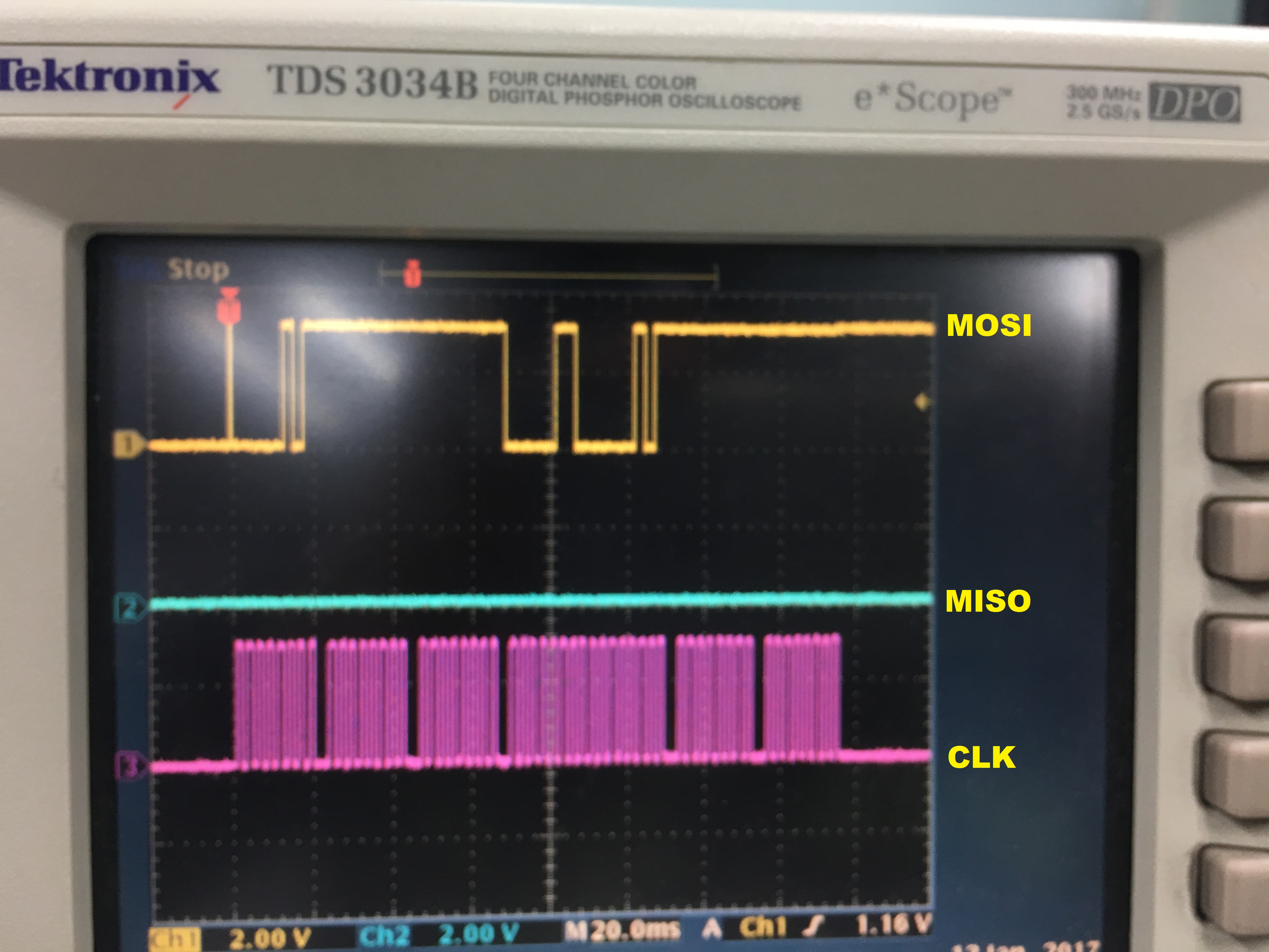
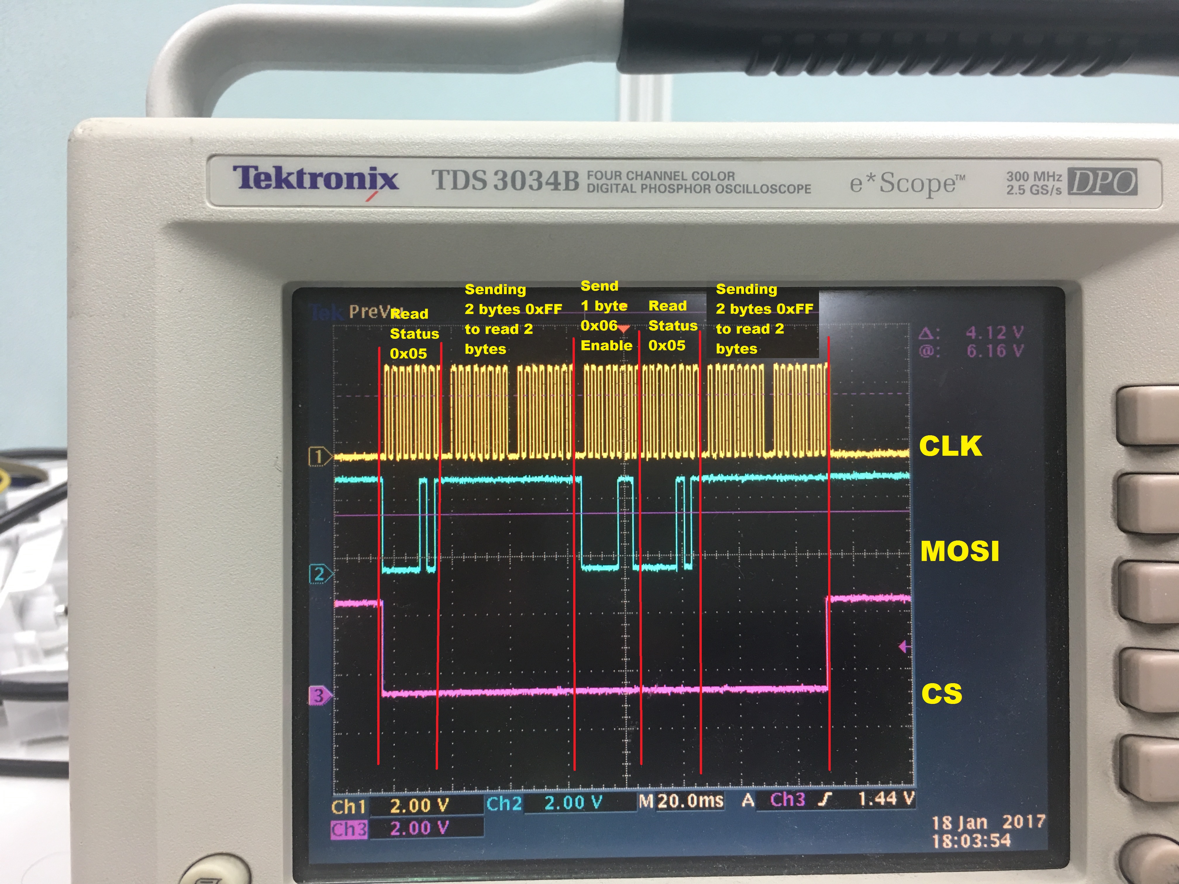
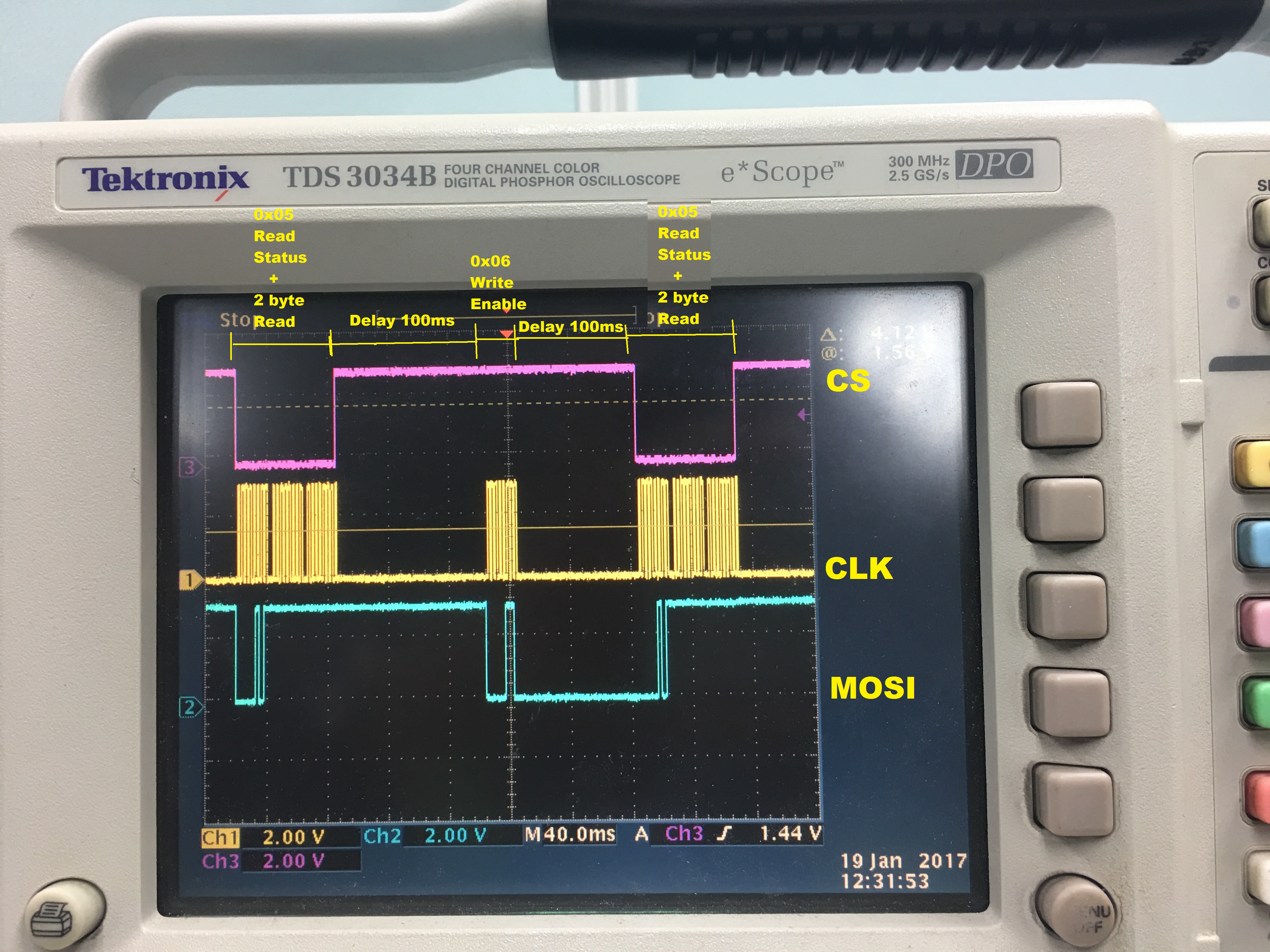
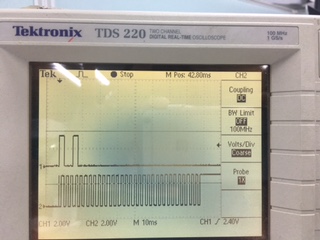
I have checked MOSI & Clock signal on Oscilloscope and getting perfectly.

but i am not able to read Manufacturer ID correctly on receiver buffer. Most of the time getting 0xFF, 0xFF or sometimes getting some random values.


Could anyone please help me figure out the issue.


Thanks & Regards,

John

  • Hi John,

    e2e.ti.com/.../563518

    Your MOSI & CLK oscilloscope screenshot did not attach properly, at any rate I'd like to see one with the MISO as well. You need to send some dummy values inside of the SerialFlash_RcvData function in order to generate the SPI CLK that allows the W25X10 to respond on the MISO line. Instead a 0xFF is interpreted since the line stays pulled up and unresponsive. Make sure that your SPI communication follows Figure 18 of the W25X10 datasheet, I've also noticed that the clock phase should be captured on the first edge (rising) and changed on the next (falling).

    Regards,
    Ryan
  • Hi Ryan,

    I am sending dummy bytes for Manufacturer ID command as below:

    uint16_t SerialFlash_ReadID(void)

    {

       uint16_t IDcode;

       // P2.6 -- 0, CS = 0 Select SPI Flash

       GPIO_setOutputLowOnPin(GPIO_PORT_P2, GPIO_PIN6);

       // Read device commands     0x90

       SourceAddr[0] = 0x90;    

       // The upper part of the device address 0x00

       SourceAddr[1] = 0x00;    

       // The lower part of the device address 0x00

       SourceAddr[2] = 0x00;    

       SourceAddr[3] = 0x00;  

       // Serial Flash send data    

       SerialFlash_SendData ( (uint8_t *)&SourceAddr[0],  4 );

       __delay_cycles(160000);

       // Serial Flash Receive data

       SerialFlash_RcvData( (uint8_t *)&DestAddr[0], 2 );

       // P2.6 -- 1, CS = 1 Release the SPI Flash

       GPIO_setOutputHighOnPin(GPIO_PORT_P2, GPIO_PIN6);

       // Get the IDcode

       IDcode = (DestAddr[0] << 8)|(DestAddr[1]);

       return IDcode;        

    }

    Then trying to read 2 bytes Manufacturer ID but not getting anything.

    The Oscilloscope screenshot as below:  

    Could you please help me to solve this.

    Thanks & Regards,

    John

  • It does not look like you have applied any of my previous suggestions, only four bytes are transmitted instead of six and the UCCKPH bit does not appear to be set.

    Regards,
    Ryan
  • Hi Ryan,

    I have changed the W25X10_RcvData function as above and Set UCCKPH bit. Now able to read Manufacturer ID successfully.
    Thank you so much. But i have doubt in serial flash datasheet mentioned supports Mode0 & mode3 only.

    Now i trying to read Serial Flash Status.

    The Recv function as below:

    void W25X10_RcvData( uint8_t *buf, uint32_t Length )
    {
      uint32_t i;
      while (UCA0STAT & UCBUSY) /*EMPTY*/; // let last Tx byte through
      (void)UCA0RXBUF; // Clear RXIFG
      for ( i = 0; i < Length; i++ )
      {
        UCA0TXBUF = 0xFF; // Dummy byte to run the SPI
        // USCI_A0 RX buffer ready?
        while (!(UCA0IFG&UCRXIFG));
        *buf = USCI_A_SPI_receiveData(USCI_A0_BASE);
        buf++;
      }
    }


    uint8_t SerialFlash_ReadStatus( void )
    {
    // P2.6 -- 0, CS = 0 Select SPI Flash
    SerialFlash_CS0();
    // Read Reg 1 Command
    SourceAddr[0] = 0x05;
    // Send Command
    SerialFlash_SendData( (uint8_t *)&SourceAddr[0], 1 );
    W25X10_RcvData( (uint8_t *)&DestAddr[0], 2 );
    // P2.6 -- 1, CS = 1 Release the SPI Flash
    SerialFlash_CS1();
    // Return Reg 1's Content
    return DestAddr[0];
    }

    But it's returning 0xFF.

  • If you can read the manufacturer ID successfully then you are using a correct SPI mode to communicate. Use your oscilloscope to confirm that your communication sequence follows Figure 6 of the W25X10 datasheet.

    Regards,
    Ryan
  • Hi Ryan,

    I am trying to Erase the Serial Flash, So i am following below steps:

    1) Read Serial Flash Status

    uint8_t SerialFlash_ReadStatus( void )

    {

       // P2.6 -- 0, CS = 0 Select SPI Flash

       SerialFlash_CS0();

       // Read Reg 1 Command

       SourceAddr[0] = 0x05;

       // Send Command

       SerialFlash_SendData( (uint8_t *)&SourceAddr[0], 1 );    

       // Receive Reg 1's content

       SerialFlash_RcvData( (uint8_t *)&DestAddr[0], 2 );

       // P2.6 -- 1, CS = 1 Release the SPI Flash

       SerialFlash_CS1();

       // Return Reg 1's Content

       return DestAddr[0];

    }

    2) Write Enable Command

    void SerialFlash_WEnable( void)

    {

       // P2.6 -- 0, CS = 0 Select SPI Flash

       SerialFlash_CS0();

       // Write Enable command

       SourceAddr[0] = 0x06;

       SerialFlash_SendData( (uint8_t *)&SourceAddr[0], 1);

       // P2.6 -- 1, CS = 1 Release the SPI Flash

       SerialFlash_CS1();

    }

    3) Reading Serial Flash Status as above

    but WriteEnable bit is not set

    Below is the Oscilloscope screenshot.

    what wrong i am doing that Enable bit is not setting?

    Thanks & Regards,

    John

  • You are trying to read the status register (05h), not the serial flash (03h), which is only one byte long (according to Section 10.2.2) and continues until CS releases it. Your next command is a write enable (06h) but do you even reset the CS pin before sending another status register read? You should view the enable bit as well to verify that it is being controlled properly.

    Regards,
    Ryan
  • Hi Ryan,

    Yes i am sending 05h only to read Status register as shown above in function "SerialFlash_ReadStatus" and it's only 1 byte. I am resetting the CS Pin.

    Below is the code:

    uint8_t SerialFlash_Erase( void )
    {
        uint8_t Temp;
        uint32_t i,j;
        // Check status register
        while(1)                        
        {                            
            // Read status register 1
            Temp = SerialFlash_ReadStatus( );        
            // Check the Busy bit        
            Temp &= 0x01;            
            if(Temp == 0x00)        
                    break;            
            for(i=0; i<10; i++);  
        }                
        // Write enable
        SerialFlash_WEnable();      
        // Check  status registers
        while(1)            
        {                                                        
            for(i=0; i<10; i++);
            // Read status register 1
            Temp = SerialFlash_ReadStatus( );    
            // Check the Busy bit
            Temp &= 0x03;                
            // If Write Enable WEL = 1
            if(Temp == 0x02)            
              break;    
        }
        // P2.6 - 0, CS = 0 Select SPI Flash
        SerialFlash_CS0();            
        SourceAddr[0] = 0xC7;
        SerialFlash_SendData( (uint8_t *)&SourceAddr[0], 1 );
        // P2.6 - 1, CS = 1 Release the SPI Flash
        SerialFlash_CS1();        

        for(i=0; i<65000; i++);        
        for(j=0; j<30; j++);
        return 1;
    }

    uint8_t SerialFlash_ReadStatus( void )
    {
        // P2.6 -- 0, CS = 0 Select SPI Flash
        SerialFlash_CS0();    
        // Read Reg 1 Command
        SourceAddr[0] = 0x05;    
        // Send Command
        SerialFlash_SendData( (uint8_t *)&SourceAddr[0], 1 );        
        // Receive Reg 1's content
        SerialFlash_RcvData( (uint8_t *)&DestAddr[0], 2 );
        // P2.6 -- 1, CS = 1 Release the SPI Flash
        SerialFlash_CS1();
        // Return Reg 1's Content
        return DestAddr[0];
    }

    void SerialFlash_WEnable( void)
    {
        // P2.6 -- 0, CS = 0 Select SPI Flash
        SerialFlash_CS0();
        // Write Enable command
        SourceAddr[0] = 0x06;    
        SerialFlash_SendData( (uint8_t *)&SourceAddr[0], 1);    
        // P2.6 -- 1, CS = 1 Release the SPI Flash
        SerialFlash_CS1();    
    }

    Could you please check the above API, m i doing anything wrong?

    Thanks & Regards,

    John

  • Could anyone please help me figure out the issue.

  • Hi John,

    It's difficult to debug the issue when no new information is provided, as I said before the write enable and second status register read commands appear to immediately follow one another without transitioning the CS pin but this could be disproved through an oscilloscope capture. You might want to try using other W25X10 instructions or read the datasheet for further clues regarding proper communication protocol.

    Regards,
    Ryan
  • Hi Ryan,

    Below is the oscilloscope screenshot with CS.  

    I am sending first 1) Read Status Command (0x05)

                                       2) Write Enable Command (0x06)

                                       3) Read Status Command (0x05) as below

    As you see my code above, for every command i select the CS and release it. But in oscilloscope not showing. Might be because of it's very fast.


    Could you please check what mistake i am doing?

    Regards,

    John

  • That CS pin needs to be toggling, either increase the sampling rate on your oscilloscope or add some delays to separate the commands. If the CS pin still fails to toggle then you know what the issue is and should address it accordingly.

    Regards,
    Ryan
  • Hi Ryan,

    I have checked CS pin by adding delay, The CS pin is toggling but when i am sending enable command it's not going to low as shown below.

    Really i am not getting why for Enable command it's not going to low.

    Do i need to send any extra byte or anything else for write command.

    Please help me to solve this issue.

    Regards,

    John

  • John,

    You're making good progress, now you just need to step through and debug your SerialFlash_WEnable function to find out how the CS pin is not being driven correctly.

    Regards,
    Ryan

**Attention** This is a public forum