


Sometimes a picture really is worth a thousand words, such as troubleshooting a motor and motor driver. This post discusses the signals that are the most commonly useful when debugging a running motor, and mentions some of the waveform characteristics that we look for in oscilloscope images.
Brushed motors
Commonly useful signals:
- OUT1 and OUT2 voltages
- Voltage spikes or dips large enough to be problematic
- Slope of voltage decay during on-time that could indicate insufficient bulk capacitance
- Look for output going Hi-Z or unstable
- VM (motor voltage)
- Voltage spikes
- Undervoltage, especially on low-voltage systems such as <12V
- Input signals
- Helps to associate timings and expected behaviors of other signals
- nFAULT
- Determine or rule out if the motor is hitting overcurrent protection (OCP), undervoltage protection, stall detected, etc.
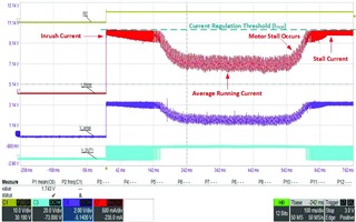
- Winding current
- Determine if the driver is chopping current
- See if output current matches input signals
In addition, it is useful to know what settings you are using such as phase/enable vs PWM, any current limits, etc.
Here are some other good resources for debugging brushed motors:
- [GREAT tutorial] Tips and tricks for testing, debugging brushed DC motors
- [Application Report] Current Recirculation and Decay Modes
- [FAQ] What interface (PH-EN or PWM) to use for controlling brushed DC motors
- [FAQ] Quick Guide to Debugging Common Issues in BLDC motor drivers (many of these points are also applicable to Brushed motor drivers)
- [FAQ] How to control voltage spikes on motor driver outputs?
Stepper motors
Stepper motor drivers often have many more features and settings than a brushed motor driver does. For many cases it is the most useful to be zoomed in to where we can see 1 full electrical cycle, and then also zoom in to 1-2 individual steps so you can see how current is being regulated at each step to look for regulation issues.
Commonly useful signals to see include:
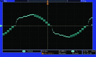
- Current of one phase of the motor (ex. Current clamp around wire leading to the motor).
- Determine where in the step indexer table the motor is
- Look for unstable currents indicating a different decay mode might be better
- A current probe works best for this, but if a sense resistor is used for current regulation you can also measure the voltage across this sense resistor.
- nFAULT
- Determine or rule out if the motor is hitting overcurrent protection (OCP), undervoltage protection, stall detected, etc.
- nHOME (if the device has it)
- VM (motor voltage)
- Look for voltage spikes or dips
- Instability
- STEP input signal
- Helps associate timing of other events
- VREF signal for stepper drivers without a built-in indexer
- Confirm VREF signal is sinusoidal or microstepping as desired
Here are some other good resources about debugging stepper motors:
- [GREAT Tutorial] Tips and tricks for testing and debugging stepper motors
- [FAQ] Debugging stepper motors
- [FAQ] How to troubleshoot common Stepper Stall Detect Issues
- [FAQ] Stepper Motor Audible Noise
- [Application Report] How to Reduce Audible Noise in Stepper Motors
- [Application Note] How to Improve Motion Smoothness and Accuracy of Stepper Motors
- [FAQ] Trapezoidal Motors vs. Sinusoidal Motors
Summary of Debug Strategies
The following table shows the types of faults that can occur commonly in motor drivers, the timing for those faults, threshold for fault detection, generic recovery method, and waveforms for further debug by triggering on the nFAULT falling edge to determine the fault. Note that waveforms are best captured using low-capacitance probes and/or differential probes measured as close to the DRV8xxx as possible due to sensitive circuits affected by parasitic capacitance.
|
Fault |
Timing |
Threshold |
Recovery |
Waveforms for further debug (trigger on nFAULT falling edge) |
|
Supply undervoltage |
VM/PVDD UVLO deglitch |
VM/PVDD UVLO falling |
VM/PVDD UVLO rising |
VM/PVDD, nFAULT (zoomed to 10us/div) |
|
Thermal warning/shutdown |
Automatic (no deglitch) |
TJ > TOTW (warning), TJ > TOTSD (shutdown) |
TJ < TOTW -THYS (warning), TJ > TOTSD -THYS (shutdown) |
VM, VCP, OUTx, nFAULT. Look for any “higher than usual” voltages on gate drive outputs or regulators to indicate overstressing or higher power losses internally. |
|
Charge pump undervoltage |
CPUV deglitch |
CPUV falling |
CPUV rising |
VCP/CP, VM/PVDD, nFAULT (zoomed to 10us/div) |
|
Overcurrent protection |
|
OUTx current above OCP |
Current < OCP deglitch |
OUTx current, OUTx voltage, nFAULT, VM (zoomed to 10us/div) |
Pulling images from Oscilloscope
An easy way to improve the resolution of the waveform images you share is to acquire the source image from the oscilloscope instead of taking a picture with a phone. Most oscilloscopes have a USB port on the front to plug a flash drive into for file transferring. Some newer oscilloscopes often include a web interface so you can pull these images from the scope wirelessly.
Teledyne Lecroy scopes: Open a web browser and go to ScopeIPAddress/instrumentscreen.html (Ex. 10.1.2.3.45/instrumentscreen.html). This will show the screen of your scope that you can right click and copy or save the image from.
Tektronics scopes: Install the free TekScope Utility shown here: https://forum.tek.com/viewtopic.php?t=140451 It supports pulling full resolution images from the scope, along with getting CSV files of the raw data among other features.
