This thread has been locked.
If you have a related question, please click the "Ask a related question" button in the top right corner. The newly created question will be automatically linked to this question.
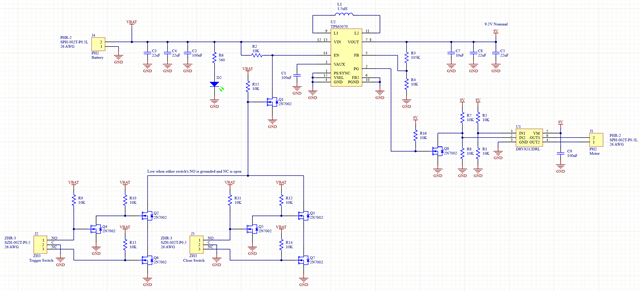
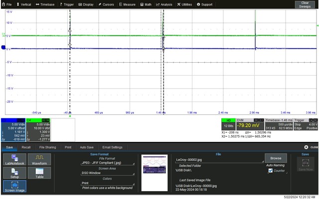
I'm using a DRV8212 to control a motor in a handheld surgical instrument. When you press the button on the handle, a voltage regulator (9.2V nominal) is enabled. Once the power good output goes high, one of the DRV8212's inputs is pulled low while the other continues to be pulled high, and the motor spins. When the button is released, both outputs are pulled high, and the DRV8212 brakes the motor. There is a secondary switch that keeps the motor on until it finishes a complete rotation. The two switches are connected to a fault-tolerant OR-ing circuit that enables the voltage regulator.
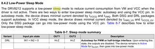
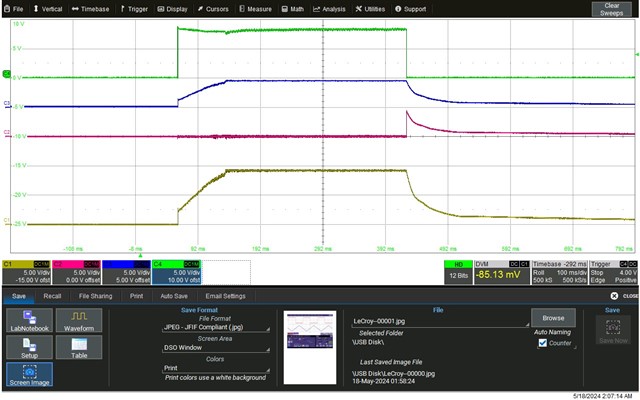
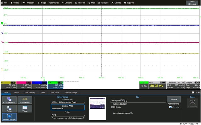
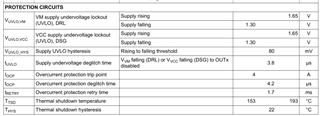
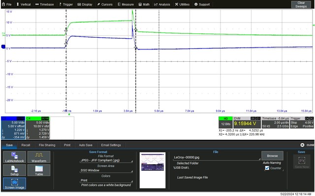
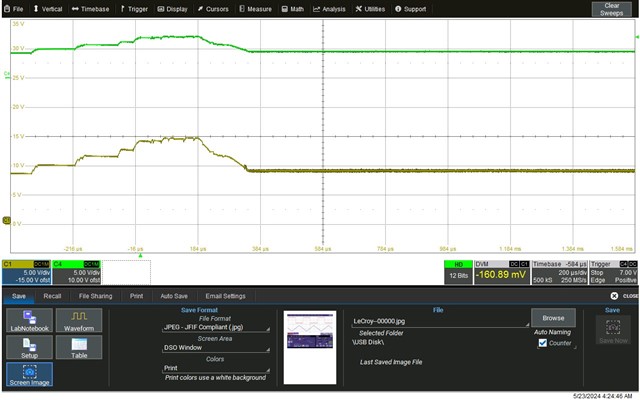
The problem I'm seeing is that sometimes the DRV8212 is going into a strange state where it no longer responds to the input signals and its outputs produce small pulses every 1.5mS. Power cycling the chip seems to be the only way out of this state. Unplugging the motor has no effect and the DRV8212 is still in the bad state when the motor is plugged back in, so I don't believe it's an overcurrent problem. When it's in the failed state, IN1 is high, IN2 is low and the outputs are both doing those small pulses every 1.5mS. The bad state is rare, but has shown up on occasion in the O.R. I've been able to get it to happen by quickly pressing and releasing the button repeatedly over five minutes or more.
I've scoured the datasheet, app notes and forums for a symptom like this but have found nothing relevant. The complete schematic is below. Help would be much appreciated.
Dan
Hey Dan,
It could be related to the autosleep function of the device. t_AUTOSLEEP is 0.9 to 2.6ms, so 1.5ms is right in between there. I would probe IN1 and IN2 to make sure they aren't both LOW for longer than 0.9ms. We've seen this a few times when people use low duty cycles and low PWM frequency result in the low time being >0.9ms, like <1kHz <10% duty. I see though that in your case IN1 is HIGH and IN2 LOW so shouldn't be the case.
Another thought would be a VM brownout condition - the 9V supply being pulled below our undervoltage level when the device starts trying to spin the motor, then VM recovers and the device tries to spin the motor again and causes a loop. But your >50uF of bulk capacitance should be more than enough to avoid this. Still, take a scope capture of the VM waveform (can be normal motor startup conditions) and see how much it dips, make sure it doesn't go anywhere near the UVLO level of 1.65V. If this was the case I would also expect removing the motor to resolve it, but as you note it does not.
A few further tests/checks I can think of:
Best,
Jacob
Hi Jacob,
I've attached a PDF with the schematic and layout. The previous schematic I posted was a slightly older version. This one matches the board I am using. Also included are JPEGs of the scope traces: one at startup and the other while it is in the failure mode.
Channel 1 is output of the voltage regulator, channel 2 is IN2, channel 3 is IN1 and channel 4 is the voltage regulator enable.
Everything looks perfect when it's in the failure mode. Supply voltage is stable, IN1 is high and IN2 is low. The motor just doesn't work.
The failure has happened on multiple boards, so it's not a one-off bad chip.
Thanks,
Dan
Hey Dan,
I believe it is the device reading an OCP. Can you measure the "small pulses" that are every 1.5ms and see if they are around 4.2us long? The device must be detecting an overcurrent event and be unable to start the motor, then auto-retrying every 1.7ms.
Can you try giving your motor a "jump start" when it's stuck in this mode? Just give it a little twist in the driving direction. I'm wondering if there's some unlucky spot on the motor where either there's a tighter tolerance or the magnets are more strongly attracted to something or friction etc, causing the OCP event and the device auto retrying infinitely while the motor is in that spot.
If that doesn't work, maybe you could add a RC circuit on IN2 to implement a short acceleration, instead of putting the device into 100% instantly? This ramp would help reduce the startup current.
Best,
Jacob
Hi Jacob,
The pulse width is about 4.5uS, and the pulses are almost identical on both motor outputs, which seems strange. I would expect one of them to be near the supply rail and one near ground based on what is being fed into the inputs.
I gave the motor a push and nothing happened. The chip appears to be latched in this bad state and nothing but a power cycle resumes normal operation. I mentioned previously that unplugging the motor doesn't change the situation. I'm having a hard time understanding why overcurrent protection would continue to keep the outputs from working even after the motor is unplugged.
Adding an RC circuit would not be desirable since this is a production board in its final stages of testing. We've been through over a year of testing so far and this problem hasn't been seen until now. I need to have confidence that the problem is completely solved.
Dan
Hey Dan,
A couple things:
Regards,
Jacob
Hi Jacob,
When I disconnected the motor, the pulsing went away, one output was at the supply voltage and the other was at ground. Therefore, OCP does appear related. The resistance of the motor is 2.4 ohms, so at 9.2V we should only see 3.83A which is under the 4A OCP limit.
As for trying your idea #2, I'm not sure how I will reproduce the failure conditions. The whole circuit works perfectly nearly all of the time.
I'll put a current probe on the motor lead just to get a idea what that looks like. I'll be able to do that either Thursday or Friday.
Maybe a little bit of added series resistance would help provide more margin for the OCP trip point?
Dan
Hey Dan,
When I disconnected the motor, the pulsing went away, one output was at the supply voltage and the other was at ground. Therefore, OCP does appear related. The resistance of the motor is 2.4 ohms, so at 9.2V we should only see 3.83A which is under the 4A OCP limit.
Ahh okay that's good to know. Let me ask design about this. It seems like the device is getting "stuck" in OCP after the first OCP event trips it, which should not be the case. I'll see what their thoughts are. Give me a day.
Maybe a little bit of added series resistance would help provide more margin for the OCP trip point?
Try adding an inductor (or ferrite bead) instead of a resistor. Either will add a series impedance on the motor and should reduce the inrush current. Adding either will come at the expense of the steady-state voltage drop during normal running of the motor, but the inductor will have less of an impact.
Here are a few threads about adding a series inductor:
Best,
Jacob
Hey Dan,
Actually one more test for you to run, try this first on your unmodified circuit:
Please set up your scope to trigger on IN1 or IN2 rising to > 5.75V, which is the abs max voltage for logic input pins. See if this scope capture triggers when the device gets stuck in this mode.
Best,
Jacob
Hey Jacob,
Your last test idea was a good one. It looks like the output of the TPS63070 is going way too high. It goes well beyond 9.2V on a regular basis during these rapid switch presses and went even higher right before the failure. In the scope captures, the yellow trace is the regulator output and the green is IN1. Seems like clamping the 9.2V supply with a zener or TVS might be a solution. I don't see anything I can do with the regulator.
Thanks,
Dan
Ahh good, yeah I think that is it then. With >7V on IN1 or IN2 the device might do unexpected things - upon violation of our specs the operation of the device can't be guaranteed. So you definitely need some clamping to keep the VM and INx voltages within the absolute maximum ratings.
Best,
Jacob