Other Parts Discussed in Thread: LAUNCHXL-F280025C, DRV8323
Tool/software:
Hi,
Last night road test my new soldered custom board also damaged, this's my third board, this time one phase (Phase A) both Upper and Lower MOSFETs damaged (D S shorted)
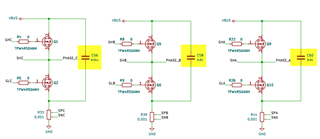
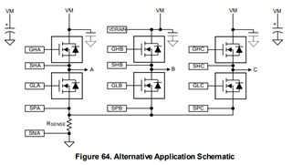
My custom board is 99.9% replicate TI reference design BOOSTXL-DRV8323RH + LAUNCHXL-F280025C combo board with minor modifications, few month road test with the combo board without any issues therefore I can concluded custom board damage wasn't caused by 1. software 2. added 100v power capacitor 3. changed to 1mOhm shunt resistor
Here's my board damaged history :
version 1 : DRV8323 damaged, TI suggest both DRAIN and VM pin should stay close.
version 2 : DRV8323 and Phase C Upper MOSFET damaged, Phase C gate resistor (20 ohm) damaged, this's follow BOOSTXL-DRV8323RH both R1 and R5 unpopulated mean IDRIVE Hi-Z 120/240mA, TI suggest lower the IDRIVE value on next design.
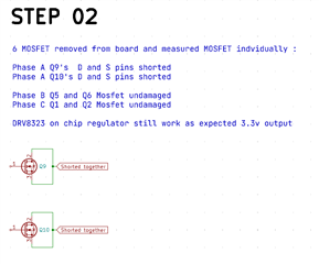
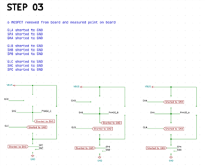
Now this time version 3 also damaged :
1. DRV and VM shorted / close together
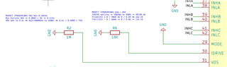
2. Gate resistor replaced with 0 ohm
3. IDRVE setting 18K Ohm to AGND that'a mean 30 / 60mA
4. VDS 1M ohm to AGND that's mean 75A cut-off
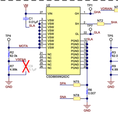
5. Shunt resistor 0.001 Ohm
6. 100V 2200uF line capacitor
More Information :
1. Both my BOOSTXL-DRV8323RH + LAUNCHXL-F280025C combo board and Custom board was tested on 6-inch skateboard motor with SpeedHz up to 200Hz 30V OK
2. BOOSTXL-DRV8323RH + LAUNCHXL-F280025C combo board road test few month with 10s Lipo pack 42v, 0.001Ohm modified shunt resistor, 30A current max. both Speed and Current modes OK
3. CUSTOM BOARD no-load test with 30V 3A power supply, 0.001 modified with Ohm shunt resistor, both Speed and Current modes without issues, SpeedHz up to 250Hz
4. CUSTOM BOARD no-load test with 10s Lipo pack 42v, 0.001 modified with Ohm shunt resistor, Speed mode survive but Current mode damaged after few tests ....
My point is :
1. what's different between BOOSTXL-DRV8323RH + LAUNCHXL-F280025C and my CUSTOM BOARD ?
2. my CUSTOM board drive 6 inches skateboard motor, speed up to 200Hz, that's reflect board signals are OK ?
3. once damaged with 42V, that's mean issues related to VOLTAGE not CURRENT ?
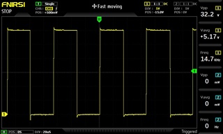
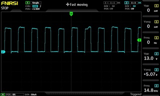
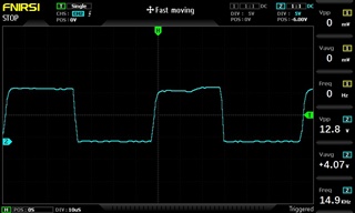
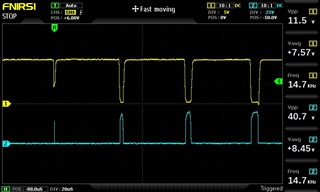
4. PHASE A both upper and lower MOSFETS damaged, that's related to dead-time signal issues ?
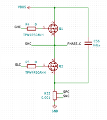
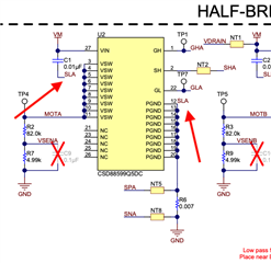
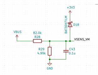
do you think the problem was caused by C56 capacitor not directly connected to GND ? however it's TI reference design ...
Sorry my design was based on KiCAD, but I would like to PM you the Gerber file if you think it's helpful !
Danny