This thread has been locked.

If you have a related question, please click the "Ask a related question" button in the top right corner. The newly created question will be automatically linked to this question.

BQ20Z655-R1: different behavior with internal and external temperature source

Part Number: BQ20Z655-R1
Other Parts Discussed in Thread: BQ40Z50, GPCRB,

Dear TI experts,


as described in the older forum posts, we had some discussions about using the internal temperature source or external on and one the other hand we had problems with jumps in the SOC at low temperatures:


https://e2e.ti.com/support/power-management-group/power-management/f/power-management-forum/1074430/bq20z655-r1-at-low-temperatures/4002813?tisearch=e2e-sitesearch&keymatch=%20user%3A422623#4002813

https://e2e.ti.com/support/power-management-group/power-management/f/power-management-forum/943315/bq20z655-r1-accuracy-over-temperature


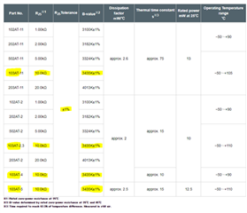
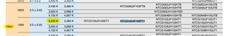
In one of our lasts tests we had six batteries programmed with the same .dfi file and then on three we set TEMP1, TEMP0 = 0,0 = Internal Temperature Sensor and on the other three we left TEMP1, TEMP0 = 1,1 = Average of TS1 and TS2 Inputs. Then all batteries were fully charged at room temperature and then two of each type were installed into the application (inside the climate chamber) and the remaining one was set into the climate chamber without application, so they were not charged or discharged at this time. Then the climate chamber was set to -20°C and the setup was left running over the weekend.


One Monday the tow applications with batteries with the internal sensor where running, so everything was fine and the two applications with the batteries with the external sensor were shut down, so the SOC had jumped to 0%. Then to verify the result we took the two batteries out of the application and put the two batteries into the application which had just set in the climate chamber without charging / discharging and the applications started again working. After letting the setup run for additional 10h the application with the applications with the batteries with the external sensor shut down. Again, this was caused by the battery reporting SOC = 0% to the application.


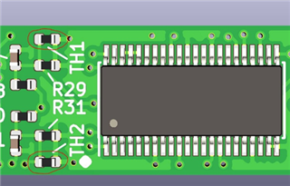
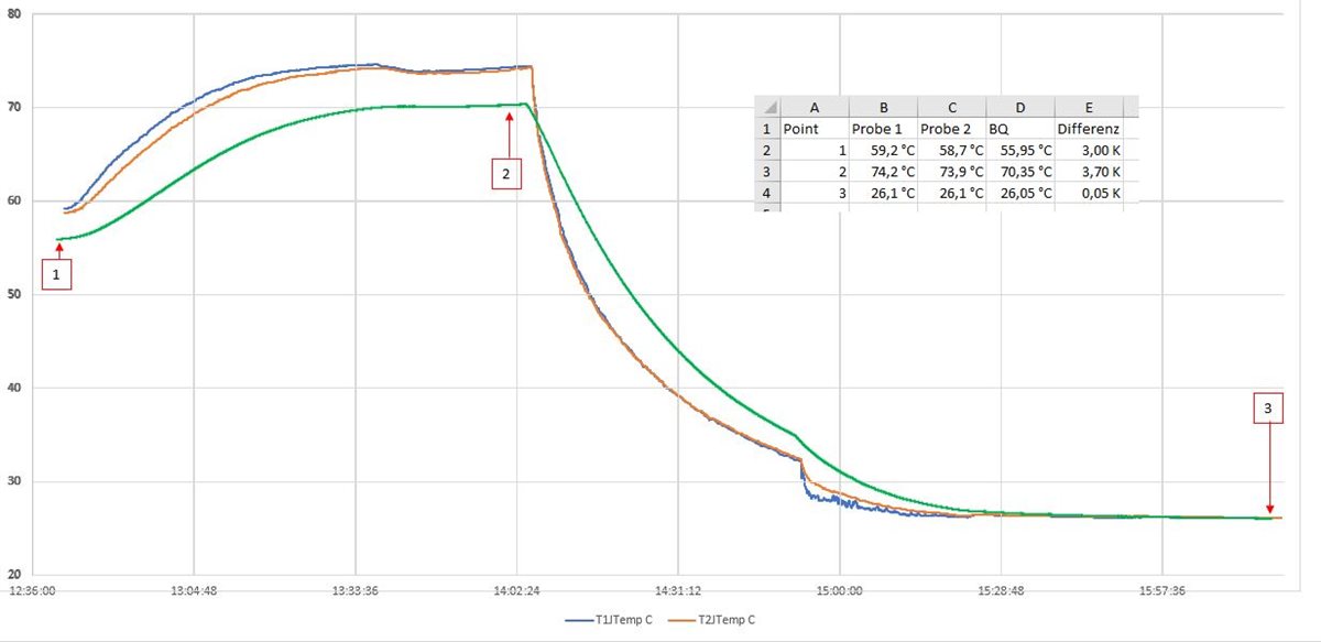
In an older test we also compared the internal and external temperature measurements with the reading of a type-J-temperature probe which was glued close to the BQ where the error didn’t seem to be too big:


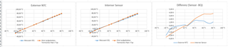
To summarize our question, is there any explanation which different influence the internal or external temperature source has on the fuel gauging?


Yours Tobias

  • Hello Tobias,

    The temperature sensor must be mounted close to the cell. The cell temperature is what is used for gauging and it can be different from the chamber because of self heating. Make sure to use the recommended temperature sensors and program correct coefficients in data flash. Calibrate temperature sensor using bq Evaluation software.

    For low temperature performance, make sure to tweak chemistry information using GPCRB tool. As mentioned in the other post, if low temperature performance is important, then switching to the bq40z50 gives more knobs to tweak.

  • Hello Shirish,


    thank you very much for your fast reply. We don’t use the BQ40z50 due to the used LCD display in this project. For the NTC we use the NTCG103JF103FT1 from TDK compared to the Semitec 103AT it has the same R_25 = 10kOhm and B_2585 = 3435K:

    From the Semitec website:

    From the datasheet of the NTCG103JF103FT1

    The external NTC are directly next to the BQ20z655 and even a little closer to the cells:

    But I think that the internal and external temperatur should be quiet close to each other because the parts are later upside down between the two cells of the battery pack.

    We also addpeded the chemistry information with the GPCRB tool and then made three more cycel with charging at room temperature and discharging at low temperatures.


    Can you confirm that when the internal and external temperature measurement return results that are close to each other the fuel gauging should be the same or is there any influcen to the gauging depending on which temperature source is selected?

  • Hello Tobias,

    Thank you for the details.

    The gauging algorithm stays the same. Temperature is an input to the algorithm. Therefore if the temperatures are identical, you should see identical results. Temperature is not very accurate in most applications, so IMO the small difference would have minimal impact.

    One thing to check is whether the thermal coupling between the bq20z655-R1 and the cell is better compared to the NTC. A height difference could result in a direct contact vs through an air gap.

    In order to debug root cause, I would suggest taking a continuous data log and then compare.

  • Hello Shirish,


    I made a test with the internal Temperature sensor of the BQ and compared it with two J-Type Temperature probes which were glued to the outside of the battery pack. I started at 60°C, went up to 75°C and then let it cooldown to ambient temperature again. At the high temperatures there is a certain offset of 3 to 4 K and at room temperature the measurements are identical. Because of this I think the calibration is fine.


    The question now is can we improve the behavior by adjusting the characterization of the internal temperature sensor?


     Here the calibration part of the .gg-file:


    [Data(Calibration)]

    CC Gain = 5.086

    CC Delta = 5.086

    Ref Voltage = 1223.70

    AFE Pack Gain = -545.96

    CC Offset = -0.251

    Board Offset = -36.9

    Int Temp Offset = 6.3

    Ext1 Temp Offset = -1.4

    Ext2 Temp Offset = -1.3

    [Config(Calibration)]

    CC Current = 3000

    Voltage Signal = 16800

    Temp Signal = 298.0

    CC Offset Time = 250

    ADC Offset Time = 32

    CC Gain Time = 250

    Voltage Time = 1984

    Temperature Time = 32

    Cal Mode Timeout = 300

    [Temp Model(Calibration)]

    Ext Coef 1 = -28285

    Ext Coef 2 = 20848

    Ext Coef 3 = -7537

    Ext Coef 4 = 401.2

    Ext Min AD = 0

    Ext Max Temp = 401.2

    Int Coef 1 = 0

    Int Coef 2 = 0

    Int Coef 3 = -11136

    Int Coef 4 = 575.4

    Int Min AD = 0

    Int Max Temp = 575.4

    [Current(Calibration)]

    Filter = 239

    Deadband = 3

    CC Deadband = 10.0

    And the log files:

    Probe J Typ Data.xlsx60 75 BQ internal.csv

  • Hello Tobias,

    Using the specified Semitec product will be the simplest and recommended solution. Other than that, the best solution we can offer is a tool and associated document.

    Updating the thermal coefficients (internal and external) is a curve fitting exercise. There is no guarantee that it is achievable but here is the document and an Excel spreadsheet that you can use.

    https://www.ti.com/lit/an/slua398/slua398.pdf

    http://www.ti.com/lit/zip/SLUA398

    Hope this helps you, wishing you the best.

  • Hello Shirish,


    thank you very much for the fast reply, I calculated the coefficients with the resistance values form the external NTC

    product.tdk.com/.../ntcg103jf103ft1.csv

    and the results were quite similar, so I don’t really expect a different behavior:


    What do you think, is it worth testing with A1 and A2 changed by 1 or not?


    I think the impact of 1% tolerance on the R_25 and B_2585 value would be much bigger one the proposed Semitec AT103 and the used TDK NTCG103… NTC.


    Can you maybe provide a similar Excel sheet for adopting the coefficients of the internal temperature sensor? Where its maybe possible to enter the measured and the actual temperature?

    Thermistor Coefficient Calculator with NTCG103JF103FT1.xls

  • I agree with your assessment that the tolerance is bigger than the difference, so it may not be worth testing with A1 and A2 changed. Unfortunately there is no Excel sheet for the internal sensor. In general, the internal temperature sensor is slightly less accurate than using a Semitec 103AT.

    Do you have logs of the discharges that we can use to analyze the differences?

  • Hello Shirish,


    after a few weeks of break, due to other projects using the climate chamber, I could go on with the testing. I compared three batteries on all three the same dfi-file was programmed. On the first battery Bat1 no adjustments were done, and the default settings of the internal temperature sensor was used. On the second battery Bat2 the average of the two external NTCs were used and on the third battery Bat3 the internal temperature Sensor with modified Coef 3 & 4 values was used.

    We know that this values normally shouldn’t be changed, but after comparing with the Excel file which is used for calculating the best values for Ext Coef 1…4 and seeing, that Int Coef 1 = Int Coef 2 = 0 it seemed that Int Coef 3 might be like with the ext Coef 3 the gain for linear part of the equation and Int Coef 4 the offset. So, we changed the Int Coef 3 to – 12483 to get a higher slope of the temperature function and the adjusted the Int Coef 4 to 617,1 to get the right offset at room temperature.

    After this changes at low temperatures, we get better results and at high temperatures it seems that we might have used a Int Coef 3 value which is a little high, so a value between the used -12483 and the default -11136 might be the solution.


    To come back to the original problem, we had with jumps in the SOC at low temperatures we will set up two batteries like Bat2 and two batteries like Bat3 and put them in the climate chamber tonight and see if still the problem is, that with the external NTC the SOC jumps and with the internal not. I hope that I have log files of this tomorrow.

    Can you give us any further information on the Int Coef1…4, Int Min AD and Int Max Temp? And if Int Max Temp must be set equal to Int Coef 4?


    Yours Tobias

  • Hello Tobias,

    Thanks. I will check it and get back to you by tomorrow

  • Hello Tobias,

    There is a better match now except for at high temperature. The internal sensor details are not available.

    I believe that there is a 4th degree polynomial function. The offset is stored in Int Temp Offset and is updated during calibration of the sensor. Make sure to calibrate at room temperature first before running the test(making this comment because it seems like there was an attempt to adjust the offset using the coefficients). Hope this helps you get a better fit.