This thread has been locked.

If you have a related question, please click the "Ask a related question" button in the top right corner. The newly created question will be automatically linked to this question.

BQ76942: I2C address

Part Number: BQ76942
Other Parts Discussed in Thread: INA228, BQSTUDIO, , , ISO1641

Hello,

on my circuit I used BQ7694202PFBR IC, for measuring cell voltages of 8 cell battery.
The problem is that my I2C scanner find it on a 0x08 address, but as far as I understand, it should be 0x10? Any idea?

Many thanks,
Kind regards,
Dejan.

  • Hi Dejan,

    The default 7-bit address is 0x08. With the R/W bit that makes the full address byte 0x10 (read) or 0x11 (write).

    Regards,

    Max Verboncoeur

  • Hello,

    I have an additional problem. On the same I2C bus I have three INA228A ICs and one BQ7694202 IC. INA228 devices have 7-bit addresses: 0x44, 0x45, 0x47, wheras BQ has 7-bit address: 0x08.

    It looks like that there is some "coexistence issue" because I2C scanner I'm using found all INAs addresses on the bus without any problems, whereas for BQ is not so easy - I got a message: unknown device at address 0x08 error.

    If I desolder all INAs from PCB, I2C scanner find device on 0x08 address without any error. Only difference I see is that INA ICs don't have CRC, whereas BQ IC has CRC. It is not sure if I can disable CRC for BQ7694202PBFR device which has CRC by default or not?

    Many thanks, Kind regards, Dejan.

  • Hi Dejan,

    You can change the Settings:Configuration:Comm Type to 0x07 for I2C 100kHz or 0x08 for I2C 400kHz, both without CRC.

    I recommend reading the first paragraph of Section 9.2 of the TRM for more details on how to do this.

    You may also consider saving this in the OTP (link to an FAQ on that) since the comm type will be reset to its default when the device is reset.

    Regards,

    Max Verboncoeur

  • Hello,

    I bought BQ76942EVM board, because I tought that it would be easier to program BQ7694202 IC (with enabled CRC and 3.3 V REG1 LDO) which is installed on my board, but it looks like that BQSTUDIO doesn't recognize ICs with CRC enabled?
    I also bought some pieces of basic BQ76942 IC which has CRC disabled, but it has also REG1 LDO disabled by default. I'm searching through the list of commands, but I don't see any command in BQSTUDIO intended to enable REG1 LDO in register? Do I need to write command manually? Additionaly, I'm also searching for command to change I2C address of device. I suppose that I need also to write it manually?
    I would like firstly to change I2C address and enable REG1 in registers, after I will be sure that everything is okay I'm going to program OTP.

    EDIT//
    I found a possibility of changing I2C address and REG value under Data Memory section.
    It looks like that most values (including I2C address) are zero by default in data memory. However I tried to change I2C address and then I clicked Write_All button, but it looks like that I2C address doesn't change. Does it change only after click Program OTP button? Do I need to fill all fields (such as CFETOFF Pin Config, DCHG Pin Config, ...) even I don't need them, before programing OTP or can I program only desired fields? I'm asking this because most of fields are zero and I'm not sure what will happen if I didn't change their values before programming OTP.

    Many thanks,
    Kind regards,
    Dejan.

  • Hi Dejan,

    bqStudio should work with I2C CRC. Can you double check the steps in this FAQ: (+) [FAQ] BQ76952EVM: Why is my BQ769x2 device unable to connect with BQStudio? - Power management forum - Power management - TI E2E support forums

    One thing to note with bqStudio is that each window is running asynchronously. For this reason, we recommend turning off the scanning function on the registers window when writing to data memory in order to prevent any collisions on the I2C bus. You should not need to write the address to OTP, you should be able to send the SWAP_COMM_MODE subcommand to change the address. Do note that if the device is reset, the address will return to its default value.

    Could you walk me through what steps you are taking to change the address?

    Regards,

    Max Verboncoeur

  • Hello Max,

    I solved a problem, it looks like that there was another instance of program in background which run simultaneosly and was causing a problem.

    After putting new I2C address in Data Memory section, address changed after pressing Write_All and then SWAP_COMM_MODE button. I was also tried to change REG12 and REG0 register values, and I can confirm that I was able to change output of LDO regulator just with pressing Write_All button.

    The question which stays open is - after I will be satisfied with chosen I2C address, REG12 and REG0 values, ... - can I program to OTP just values of desired registers or I need to properly fill fields of all registers (even all functionalities will not be used) such as DFETOFF pin config, TS3 pin config, ... and then write to OTP?

    Is any special procedure needed before writing to OTP or when I will be satisfied with settings, I just press Program OTP button and that is all? BQ76942 IC is supplied from 8S battery, so around 30 -32 V is on BAT pin present.

    Any idea why is different setting for I2C that runs on 100 kHz and I2C that runs on higher frequencies?

    Many thanks, Kind regards, Dejan.

  • Hi Dejan,

    I'm glad to hear the issue is resolved!

    You can program the OTP of specific registers. There shouldn't be any special procedure aside from what is detailed in the OTP FAQ I linked a few replies ago, most notably the BAT pin should be at 12V. I recommend giving it a quick read if you haven't already.

    With that, you should just be able to hit the Program OTP button and the UI will tell you if there is anything you need to do.

    The 100kHz I2C speed setting is available in the case that the 400kHz timing requirements (rise time, high time, etc.) are not achievable by the system.

    Regards,

    Max Verboncoeur

  • Hello Max,

    I made a changes in registers:
    REG12 Config :: 00 (default) -> 0D (new value)
    REG0 Config :: 00 (default) -> 01 (new value)
    I2C Address :: 00 (default) -> 60 (new value)
    Alert Pin Config :: 00 (default) -> 29 (new value)
    TS1 Config :: 07 (default) -> 0B (new value)

    And everything works as configured, which is really great!
    Additionaly, I just would like to disable shutdown and sleep mode, in a way that after power is provided to BAT/LD pin of BQ76942, device goes directly to normal mode and stays there until battery is disconnected. Is this configured by 12. bit (SHUT_TS2) and 8. bit (SLEEP) of register Settings:Configuration:Power Config? I assume that value of 12. bit of this register must be 1 (instead of 0 which is by default) and 8. bit must be 0 (instead of 1 by default) to achieve intended operation.

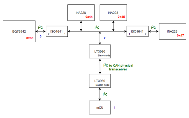
    The biggest problem I'm dealing with now - it looks like that BQ76942 is not "compatible" with INA228 devices or LT3960 (I2C to CAN physical transceiver) which are placed the same I2C bus.

    Block schematic (I2C addresses of devices are shown in red color):

    There is no difference if I connect I2C scanner on mCU's I2C side (shown by number 1 in blue color) or LT3960 slave's I2C side (shown by number 2 in blue color), I get every time the same output from I2C scanner:

    Scanning...
    Unknown error at address 0x30
    I2C device found at address 0x44  !
    I2C device found at address 0x45  !
    I2C device found at address 0x47  !
    done

    As you can see, device 0x30 (BQ76942) is detected, but with unknown error at this address. I also tried to communicate with BQ76942 device from mCU's I2C side, but communication doesn't work - BQSTUDIO doesn't detect any device.

    Only when I run I2C scanner on the BQ76942's I2C side (shown by number 3 in blue color), I got next result:
    Scanning...
    I2C device found at address 0x30  !
    done

    In this case, the device is detected properly, without any error at this address. By the way, it is completely right that other I2C devices are not detected from this side of the I2C bus, because ISO1641 isolator passes clock just from side 1 to side 2 and not vice versa as well. When the EVM board is connected to this side of the I2C bus, BQSTUDIO detects the BQ76942 without any problem.

    Honestly, I'm not sure if BQ76942 is incompatible with INA228 on the same bus (separated by isolators) or there is an incompatibility with LT3960 I2C to CAN transceiver. I also tried to eliminate I2C isolator which is placed between I2C side of BQ76942 and I2C side of INA228 (0x44 and 0x45), but result is the same - error is detected at address 0x30. This means that the isolator is not a source of a problem. I also used an oscilloscope to check if there is something unusual on the I2C waveform, but both SDA and SCL waveforms look great.

    I also tried to change Comm Type settings of BQ, from default (0x00) to (0x07) and (0x08) to check if higher speed would help, but there is no difference, still the same output with error detected at 0x30 address.

    In LT3960 datasheet is mentioned (on page 16) Transmit Dominant Timeout Function which should be solved by increased SCL frequency. As I mentioned - I tried to increase SCL frequency but the problem stays present.

    Do you have any idea what could cause such problem?

    //Added :: 22/11/2023 18:30 UTC

    I'm digging in to datasheets of ISO1641 isolator and LT3960 I2C to CAN transceiver. For both ICs is mentioned that they don't support clock stretching, however it looks like that BQ76942 device do clock stretching occasionally. I'm thinking now that this could be a problem, but it is not completly sure because error on the address was detected also when isolator was removed and I2C scanner was connected to I2C side of slave LT3960 device...

    Does the BQ76942 perform clock stretching during reading cells voltages? What about the setting Settings:Configuration:Comm Idle Time ... in datasheet of BQ76942 is mentioned that this setting could reduce clock stretching frequency?


    Many thanks,
    Kind regards,
    Dejan.

  • Hi Dejan,

    Disabling SLEEP mode is as simple as setting Settings:Configuration:Power Config [SLEEP] = 0. The SHUT_TS2 bit won't disable SHUTDOWN mode, it just disables using TS2 as a wake signal. Disabling SHUTDOWN mode is a little more in-depth. I recommend going through this FAQ (link) for a list of the different faults that can send the device into SHUTDOWN mode, and then disabling each in the settings.

    The device can clock stretch when it is fetching data or is otherwise busy. It could be the source of this behavior. I don't know if increasing the Comm Idle Time will resolve this as that just allows the HFO to continue running for longer, but on the first transaction (detecting the device on the bus) it may not have an effect as the I2C will likely already be idle.

    You may want to try reading the waveform of the I2C bus both at the MCU and at the bq76942 at the same time to compare and see if there is anything being lost in either direction.

    On a side note, we typically request that any questions that are not directly related to the original question are put in a new post, both for our tracking purposes and to provide better visibility for anyone with a similar question. No need to do that for this question as I've already replied, but in the future, please ask any new/related questions in their own thread.

    Regards,

    Max Verboncoeur