This thread has been locked.

If you have a related question, please click the "Ask a related question" button in the top right corner. The newly created question will be automatically linked to this question.

TPS63900: Using a DC/DC converter with LiSOCL2 Primary Cell for IOT application

Part Number: TPS63900
Other Parts Discussed in Thread: TPS7A05, TPS62840, TLV431

Dear all, 

I have a designed a board integrating a Lora MCU (+ sensors) powered from a low powerLow noise/low voltage dropout LDO MCP1700-3302 with 170mV droupout voltage. My board is powered with a 1x D-size primary Cell with 500 mA current capability 3.6VDC with a Load when I use a new cell. 

when the board is in sleep mode, the current leakage is 10uA @ 3.3VDC (=LDO Vout), and 89mA-110mA during TX mode.

I figured our the LDO is not working properly when VBAT <= VOut + DropOutVoltage, i.e. 3.45VDC , I see voltage drop and glitches on Vout leading to MCU resets due to internal  brown-out circuit.

I was thinking to power the board directly from the Primary cell without using a DC-DC converter, but at high temperature the primary cell voltage can increase to 3.8VDC and this can damage or decrease Lifespan of some sensitive components mostly sensors (at 3.8VDC , the Voltage is in the Absolute Voltage Zone) , and using a zener-diode at 3.6VDC is not best solution for ultra-low-power application.

Currently I am hesitating between a LDO or a Buck-Boost converter adapted to 1x LiSOCL2  primary cell:

- I can use a buck-boost converter like TPS63900 but I am worried about Voltage Ripple noise +/-50mV , which can be noisy for sensors. Noise problem can be maybe solved by using ferrite Bead or electrolyte capacitors on the Vout on the voltage output . 

Or using a LDO TPS7A05, your specs mention it's compatible with 1x LiSOCL2  primary cell, but I am afraid to face the same problem than the MCP1700-3302 and have unexpected behavior when VBAT <= Vout + DropOutVoltage

do you have any suggestion or solution to advice ?

Many thanks, 

damon

  • I was also thinking to use the TPS62840 as PWM mode can be stopped when sensor are enabled, and can solve voltage ripple noise issue. But it's a step-up, Not sure it can work properly if VBAT < Vout .

    thanks, damon

  • Hi  Damon,

    Since output voltage of battery is not constant, always a big range, so, i think a buckboost converter is a best solution to extend the life of battery.

    It can help battery to discharge to a lower level of input voltage.

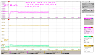
    For output ripple, Please check the Iout_high part, it is similar with your application and the ripple is about 20mV. 

    Regards

    Tao

  • Dear Tao, 

    many thanks for your quick answer, much appreciated, I already bought an evaluation board to test it.

    If the battery voltage is lower than 3VDC , the MCU and some electronics can not work properly. The UVLO threshold voltage is too low for this application ( 1.7VDC)

    Can I use voltage divider on EN PIn input and switc off the TPS63900 if the battery  voltage is low ?

    On the specs page 5,  I can see VIL  MIN IS 0.4VDC and VIH MAX 1.2VDC.

    between 0.4VDC and 1.2VDC I don't know what would be the TPS63900 behavior .

    Thanks, 

    damon

  • Hi  Damon,

    Since the behavior of TPS63900 is not sure bwtween 0.4~~1.2V. Divider is not a good idea to get a precise 3V UVLO_OFF.

    We need much more external components, may be 1*TLV431+1*FET(signal level)+4*0402 package for resister  and capacitor, is it ok for you?

    Regards

    Tao

  • Dear Tao, good suggestion... I will have a look to this solution. Currently my design is working well with 9uA of current cons. @3.3VDC in battery saver mode, I would like to keep this ultra  low power consumption.  if you have a reference design please share it with me .thanks ;-)

  • I found this reference design, maybe you were referring to this one.

    www.ti.com/.../slva987a.pdf

  • Hi  Damon,

    Correct.GrinGrinGrin

    Regards

    Tao