This thread has been locked.

If you have a related question, please click the "Ask a related question" button in the top right corner. The newly created question will be automatically linked to this question.

LM27761EVM: Two possible voltage output.

Part Number: LM27761EVM
Other Parts Discussed in Thread: LM27761, LM339A

According to the data sheet, the formula for Vout is -1.22*(R1+R2)/R2

where Vfb should be (1.22) between 1.202V and 1.238V

So I choose R1=115K and R2=499K to get Vout=-1.5V

However Vout turns out to be either -1.5V(with Vfb=-1.219) or -2.31V (with Vfb=-1.877)

I verified that Vfb is connected to the voltage divider.

What am I doing wrong?

What in the chip should be forcing Vfb to go to -1.22 instead of -1.877?

Thank you in advance for your assistance.

  • Hi Serge,

    This could be due to a bad FB pin contact to the EVM. Can you double check this or re-solder the unit once again?

    What is the input voltage you are using?

    Could you also share a scope shot of the charge pump output cap CPOUT as well as VOUT?

    Best regards,

    Varun

  • Hi John,

    Thank you for addressing my issue. Allow me to clarify the scenario.

    We actually tested successfully the evaluation board (EVM) and decided to "duplicate" the design on our boards.  2 circuits one with -5V output voltage, the other with -1.5V. The input voltage in both cases is +5V. 

    The design of the EVM board was incorporated on our cards in two phases:

    First phase using tantalum capacitors (this is not recommended in the data sheets).  Application for -5V output generated -4.26V; due to the big ESR of the tantalum capacitors.  Application for -1.5V output, generated -1.48V (good enough, in spite of tantalum capacitors: big ESR).

    Second phase using ceramic X7R (very low ESR) instead of X5R capacitors.  Application for -5V output generated -4.77V (good enough).  Application for -1.5V generated either +0.77V or -1.5V on power up. The values that were declared previously were done without a load on the -1.5V output.  

  • ToTI_1.docx

    This is the scope output that you requested.  I also added our schematics.

    Thank you.

  • Hi Serge,

    Thanks for the information and the scope shots. In the scope shot where the output is wrong, even the CPOUT voltage is wrong. CPOUT can only be -VIN and the pass transistor of the integrated LDO connects VOUT to CPOUT. It could be there is some other +ve voltage getting leaked on to the VOUT rail from some other component connected to this rail. Could you physically disconnect everything on this rail, so that there are no other components after C912?

    Can you also share the layout of the LM27761 on your board? Is the thermal pad connected to PCB GND? 

    Best regards,

    Varun

  • Hi John,

    It is interesting that I had similar taught as you do.  I did cut the load off the inverter and measured +ve to be about +1.66V. This is due to connections to GND pins of (4) LM339A and their associated decoupling caps.

    So please answer the following questions:

    That positive voltage (+ve) will be overridden by the output of the DC/DC inverter (VOUT) when all is working, right?

    Do I need a diode clamp to GND to suppress +ve until the DC/DC inverter catches up?

    Could +ve be damaging the DC/DC inverter?

    See attached document. The artwork is also included.  As you will see, the thermal pad of the DC/DC inverter is connected to PCB GND. Please note that there is an inner GND plane (and also an inner power plane and more).

     ToTI_2.docx

  • Hi Serge,

    Please see my answers below: 

    That positive voltage (+ve) will be overridden by the output of the DC/DC inverter (VOUT) when all is working, right?

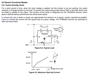
    It could be that the LM27761 is not able to startup properly when the output is +ve. Also there is a chance that the LM27761 is current limited if the +ve supply is able to source more current

    Do I need a diode clamp to GND to suppress +ve until the DC/DC inverter catches up?

    Yes would be good to add a Schottky diode to GND. Please see below


    Could +ve be damaging the DC/DC inverter?

    It could get damaged. Could you try the diode implementation with a fresh LM27761 unit?

    Best regards,

    Varun