This thread has been locked.

If you have a related question, please click the "Ask a related question" button in the top right corner. The newly created question will be automatically linked to this question.

BQ24650 charging problem

Other Parts Discussed in Thread: BQ24650

Hi,

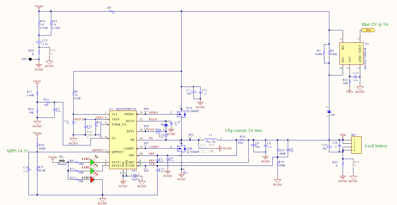
I’m using BQ24650 to charge a 3-cell Li-Ion battery pack and have some problems.

We overlooked the input RC filter. How important is it? Without it, will the circuit still work without protection?

Is D1 on the datasheet required? We are using a DC power supply instead of the solar panel.

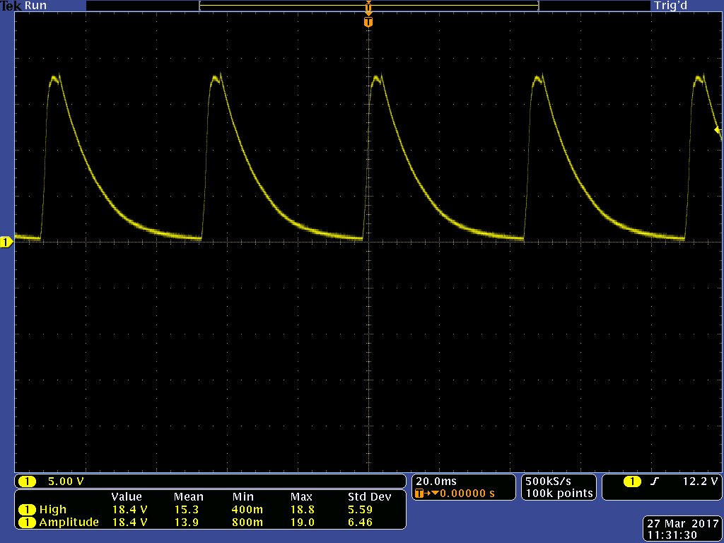
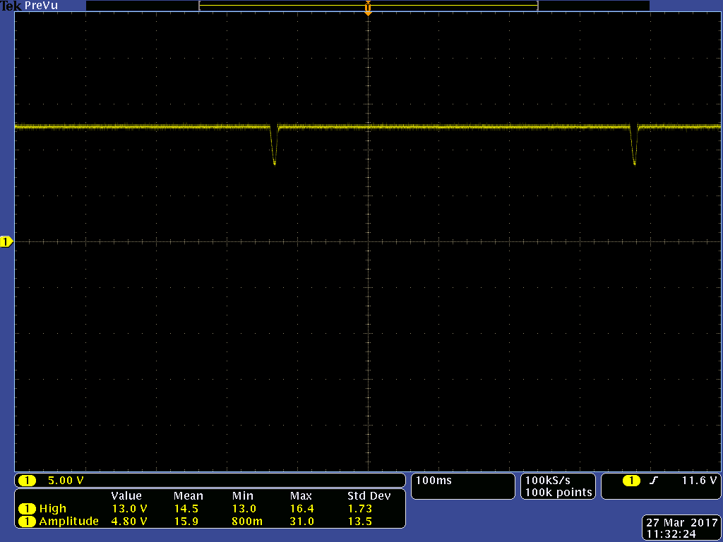
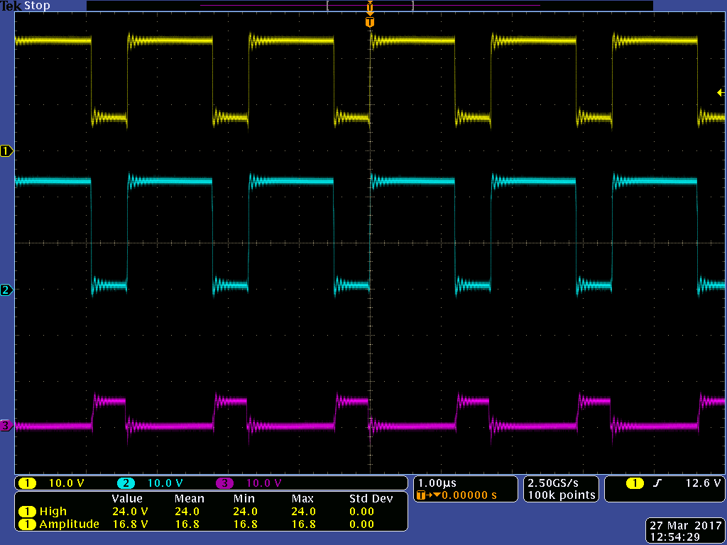
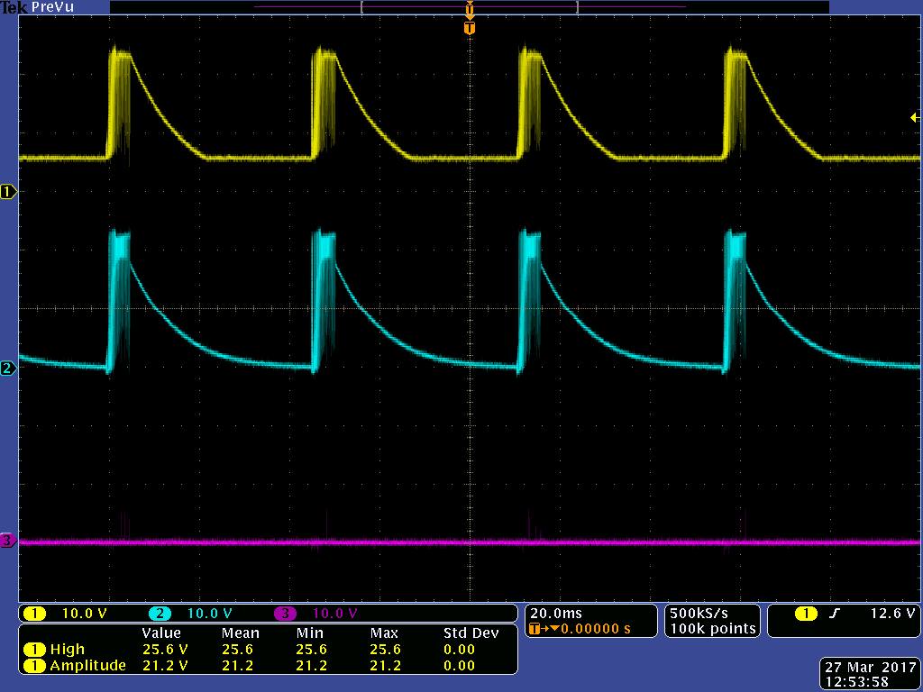
The attached is the scope capture of PH pin (14). The regulator seems to start switching, but only for a short period of time.

Thanks for your help.BQ24650.docx

  • Hi Shang,

    The device will operate without the input filter. It will just be vulnerable to large input spikes.

    It is probably best to have a blocking diode after your input. Regardless of what your input source is, the battery has a direct connection back to the input through the high side body diode.

    Looking at your schematic in the document, I see that your REGN cap is only 0.1uF. Try replacing this with a 1uF cap. This will probably help the internal LDO stability when it tries to drive the low side FET.
  • Hi David,

    Thanks for the suggestion and I'll try this first thing in the morning.

    I guess I should also replace the VCC capacitor to 1uF.

    Forgot to mention earlier that I tried putting a large electrolytic cap (100u) at the input and the battery charging function worked, although the stability was marginal.

    I'll test the circuit with modifications and post the results.

    Thanks again.

  • Shang,

    I think replacing the VCC cap and REGN cap with 1uF caps will help. If you look at the datasheet, those are both input/output of LDO's. Let me know how it goes.
  • Hi David,

    I replaced the caps to 1uF, but that didn't help.  I begin to suspect if that's the layout problem.

    Layout capture attached.

    Thanks again.Problems.docx

  • Also here's the BTST pin capture.

    If I understand it correct, that pin should display switching signal, but it only happens every 45ms or so.  Puzzled...

    BTST.docx

  • Shang,

    Thanks for the additional info. That's unfortunate that replacing the caps didn't help. Regardless, I would leave the REGN and VCC caps as 1uF for best performance.

    The BTST pin is not the switching pin, but rather the high side FET gate drive pin. The switching signal is actually at the PH pin. It looks like the converter switches everytime BTST drops 4V, which is correct.

    A couple things:

    Could you show me traces of high drive and low drive together? I am curious to see what is happening there. I only need to see a few periods. If I can see Vbat that would also be helpful.

    Could I also see a waveform of what MPPSET looks like with a battery attached?

    Can you double check to make sure the BTST diode is the correct polarity? It most likely is, but you can't ignore the low-hanging fruit.

    How did you guys solder on the TS resistors? You said you soldered them on by hand, but I only see the QFN pin pad for TS. Is that pin floating or shorted to something else?
  • Hi David,

    The screen captures are attached.  The diode polarity is correct.    We soldered the TS resistors on the board with a short wire (<1cm) and it shows 1.99V.

    Thanks for spending time to help us out.Problems2.docx

  • Hi Shang,

    No problem!

    I apologize for the ambiguous wording - I should have said hi drive and low drive waveforms, rather than traces (meaning scope traces). This is my fault.

    However, your voltage at MPPSET is really interesting. That actually looks like the battery detection waveform. This makes me think that you do need the diode D1 on the datasheet. Was this waveform taken with a battery inserted, or without one?
  • Hi David,

    I tried shorting D1 on the BQ24650EVM development board and it was working fine.  I removed C4 and it was also working fine.  That says the diode and the input filter are not absolute needed to have the circuit functioning, although good to have.

    I also did some more measurement as attached.  It seems that my board is really noisy and some large ringings as well.  Included the board layout and hopefully you can point out where the problems, so I don't make the same mistake again.  By the way, all the measurements were taken with battery connected.4380.Problems.docx

    Thanks.

  • Hi Shang,

    I have attached a picture of the layout with some specific comments/graphics, hopefully they are helpful for the next revision.

  •  Hi David,

    We’re experiencing some problems and hope you can help us to solve them.  In general the battery charging function works.  We pretty much copied the design (including the layout) from TI’s development board.  One obvious difference is the reverse protection diode on the development board has been replaced with a 0-ohm resistor.  The reason is that the solar array comes with blocking diode built-in and we don’t want to lose additional power.  

    First problem is that when the battery is removed, the STAT1 LED still turns on (our board) while the development board turns off.  Second thing is when the (18.5V) supply current is lower than the battery charging current, the input voltage/current fluctuates although it is maintaining the voltage (a few volts) above the MPP set point.  It never reaches the MPP set point. The development board does not do that.  It stays pretty steadily at the set point.  I shorted the reverse protection diode on the development board and it still works fine.  That indicates the reverse protection diode is not needed.

    Also the following are the captures of the battery connector for my board and TI's development board, when the battery is NOT connected.

    Thanks.

    VBatt of our board when the battery is not connected.

    VBatt of TI's development board when the battery is not connected.

    BTST, HIDRV, LODRV when the battery is being charged.

    BTST, HIDRV, LODRV when the battery is removed.

  • Hi Shang,

    Stat1 Pin always low? How many PCBA with this proble? it may be soldering problem.

    If the power of the power supply higher charging power, Vin will higher VMPPT.

    Alen Chen
  • STAT1 LED turn ON about 1 second after power on.  When I remove the battery, it turns OFF and turns ON again in about a second.

    The power supply is 18.5V and the VMPPT is 14.1V, but it never dropped to 14.1.  It's fluctuating about 17V or so when the power supply's current can't support.  Ideally it should be 14.1V, but I didn't see that.

    One place I suspect may be C18.  This additional cap may have messed up the MPPSET timing/threshold.

  • I just confirmed that C18 was the problem for the V_MPPT not stable.  It works fine after removing it.

    However, the LED problem is still there.  When I remove the battery, the STAT1 LED turns off briefly and turn on again.  Haven't figured out that problem yet.

  • Hi Shang

    Don't worry about the LED. Stat1 is blinking when BQ24650 is in battery detection phase.

    Alen Chen