This thread has been locked.
If you have a related question, please click the "Ask a related question" button in the top right corner. The newly created question will be automatically linked to this question.
Hi,
we use the BQ24610 for battery charger base product,
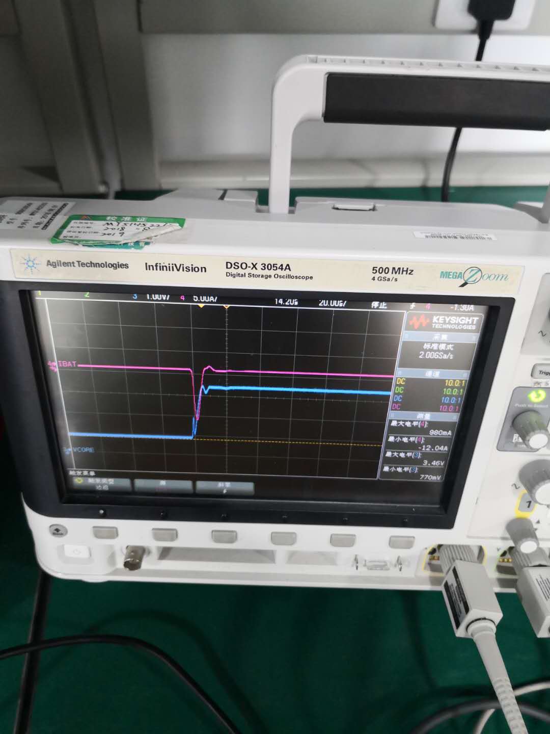
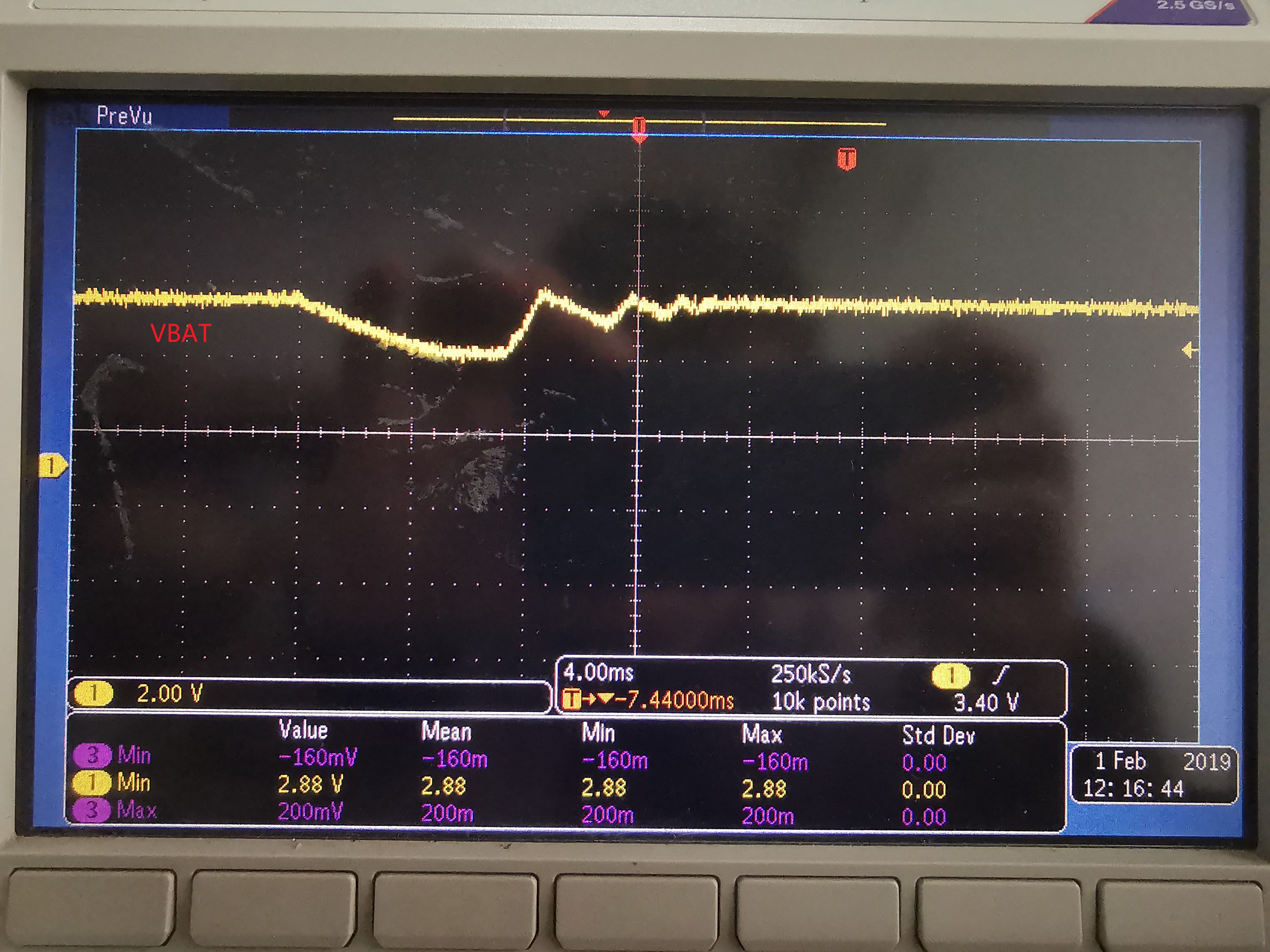
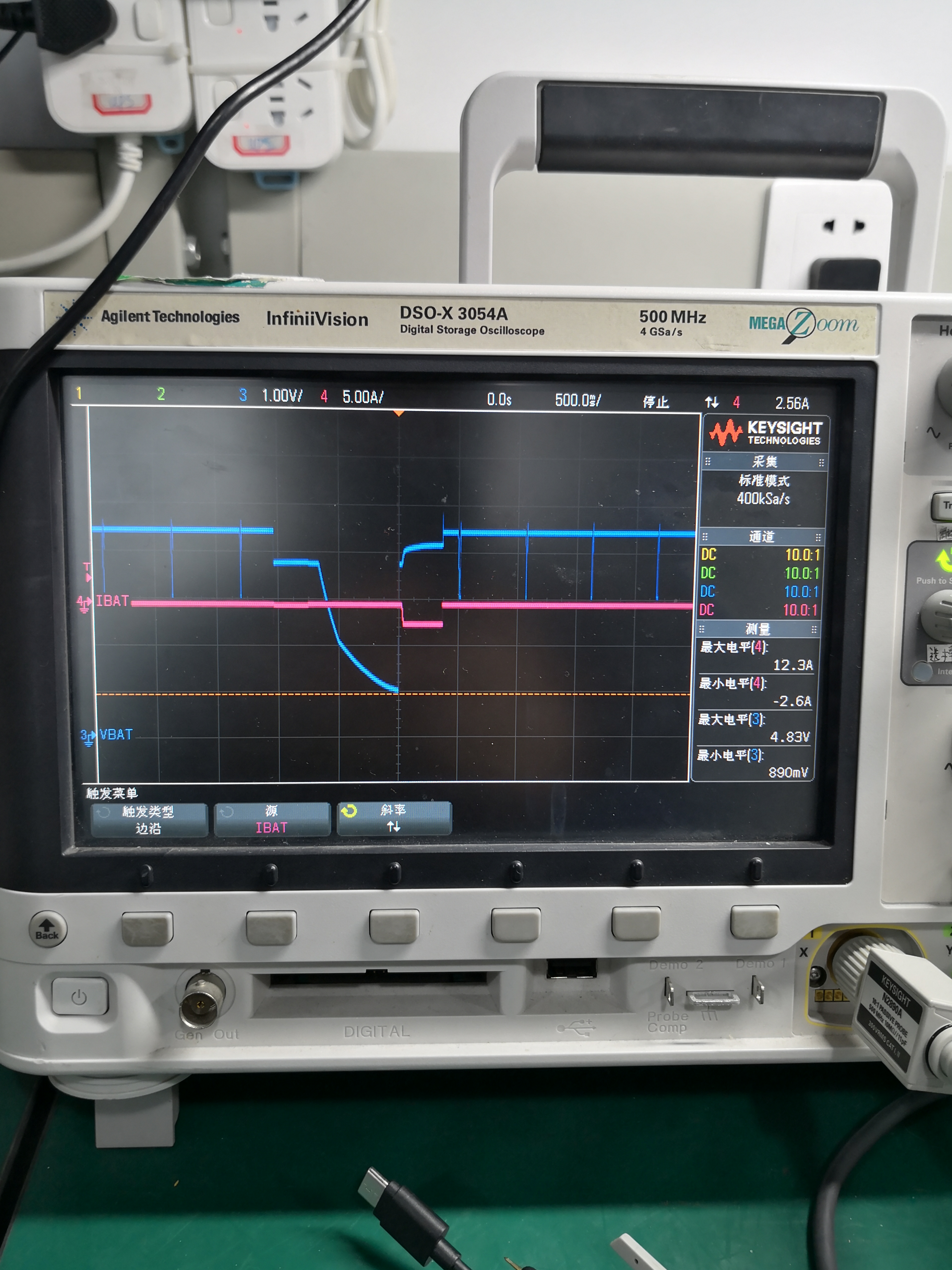
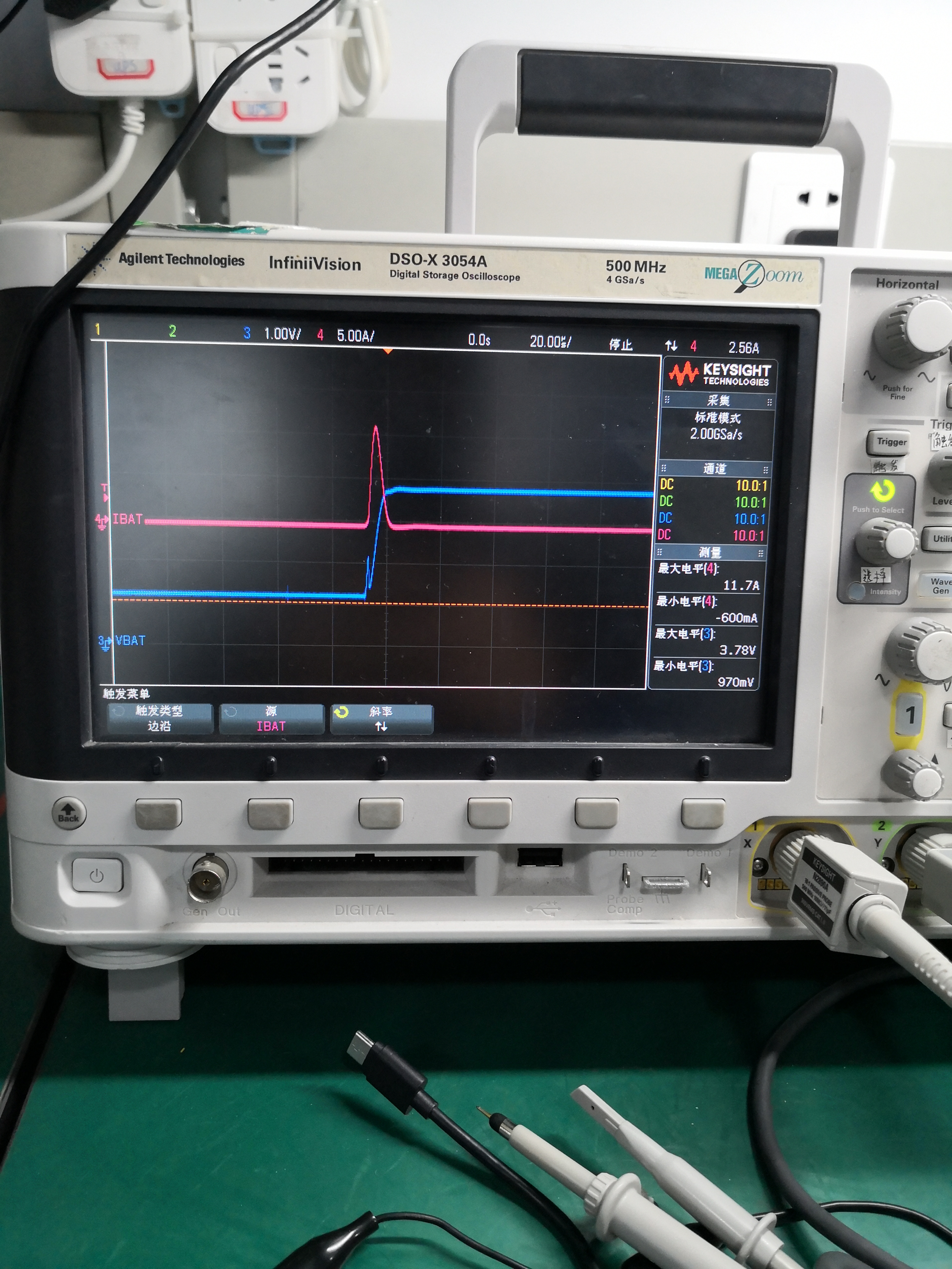
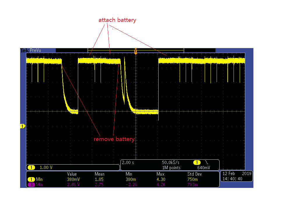
but we find there is a strange behavior on the charger IC, please help check the test waveform in the attached file.
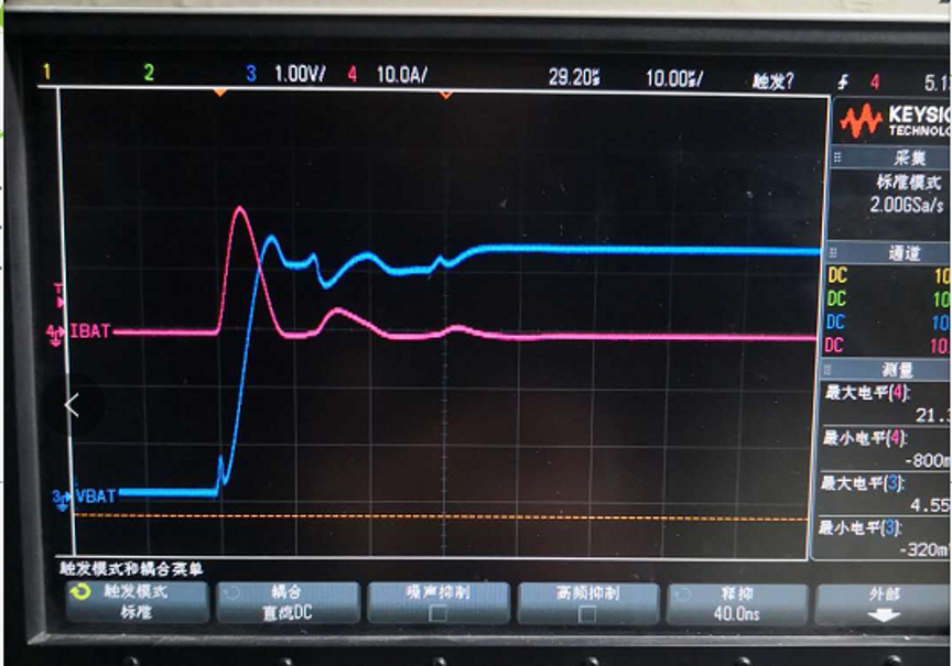
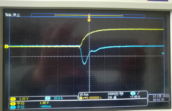
and we also find the large current from battery to charger IC during the battery insertionBQ24610 design.pdfBQ24610 design.pdf
Hi Joel,
what does "pre-biasing 30-uF of ceramic capacitance to 3V" mean?
the 3V is FB pin?
and there is another question:sometime, we find that the VBAT pin is about 0.8V when battery is not attached. you can check that in my test waveform.
Note: in my 1st waveform, there is CH, name is VCORE, that actually is VBAT,
BRS,
TONY L
Hi Joel,
After Chinese Holiday, I will check the inrush current after the prebias added.
To see if the behavior is the same without the charger, try hipre-biasing 30-uF of ceramic capacitance to 3V and then apply your battery and monitor the voltage and current
>> we found that on some boards, the VBAT is 0.8V as battery is not attached, and after the battery is attached, the charging can't work well.
BRS,
TONY LIU
Hi Joel ,
when the adapter is not attached, the test waveform can be found as below, the inrush current is so high. is there any soution suggested for so large inrush current? tks a lot in advance!
we also test the inrush current on your EVM board without power adatper attached, please check the below:
BRS,
TONY LIU
Hi Joel,
so this voltage dip 0.8V is reasonaable, correct?
I add the LDO 3.3V voltage on the VBAT, after this work arroud is added, the inrush current can be reduced down. please help review the attached file. tks a lot!
but we still don't know how to resolve the inrush issue as the adapter is not attached.
Battery Inrush Current 2019-0212 - 副本.pptx
BRS,
TONY LIU
Hi Joel,
tks a lot for your support,
I compare our shcematic with your EVM schematic, we find that there is a mistake, we don't add the 0.1uF capacotor on the SRP,
is there any risk? will this missing capacitor cause malfunction on charging, or only impact the current accuracy?
BRS,
TONY LIU