This thread has been locked.

If you have a related question, please click the "Ask a related question" button in the top right corner. The newly created question will be automatically linked to this question.

TPS2373-4EVM-758: the voltage of vc_in is half that of VDD and pd is not recognized by the pse (802.3 at)

Part Number: TPS2373-4EVM-758
Other Parts Discussed in Thread: PMP21318, UCC2897A, TPS2373

Hi, 

1.My design is based on 8228.PMP21318_RevA(001)_Sch,please refer to the attachment for details.

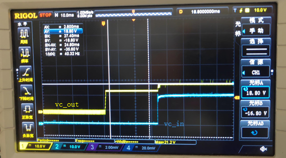
2.In the test,the voltage of vc_in is half that of VDD ,if VDD=40V,VC_IN=20V.then the vc_out =20V.But the maximum voltage of VDD of UCC2897A is 16.5v.Is there something wrong with the transformer?

3.In the test,pd is not recognized by the pse (802.3 at).Rclsa=63.4 and Rclsb=90.9,is there something wrong with the CLSA and CLSB?

4.I have a question to confirm,is the switch of UBNT us-xg-6poe compatible with this PD?  AND what do I need to set?

Looking forward to your reply!

Thanks!

2474.8228.PMP21318_RevA(001)_Sch.PDF

  • Hi Congyu,

    2. The transformer is deigned for a ~12V bias winding and looks correct (we have not changed it). The VCOUT in the datasheet is spec'd to be max 15V. So 20V does not make sense. Can you send your schematic?

    3. Can you order TPS23880EVM (BT PSE) and see what the GUI sees when your board is connected? An AT PSE should process the 63.4 ohm class resistor.

    4. Its datasheet says that it is compliant to BT standard and PoE++ standard. We designed TPS2373 to be compatible to both. So it must be either your board or the PSE. I recommend checking wih 23880EVM because the GUI can check if there is fault.
  • Hi Darwin,

    My schematic is the same as 2474.8228.PMP21318_RevA(001)_Sch.

    In the test, I input 40v from J1,Vout is 12 v.And the input current shows 78ma. In fact, I only connected two leds,no other load.And the transformer has obvious heating phenomenon.I'm afraid the transformer was damaged by the high temperature when I was welding it,because I blew the transformer in with a hot air gun.

    We will consider buying TPS23880EVM (BT PSE) for test.

    PD1.pdf

  • Hi Darwin,

    I'm now powered by the Adapter, so I can get an output of 12V, and the TPH output is low.Now the key problem is that VC_in is half of VDD (VDD=40, VC_in =20V),i don't know what will cause this phenomenon, I have replaced the transformer.AND i am now sending you some test waveforms.As shown below.(The bit number refers to my schematic diagram(PD1.pdf))

    1.Q8&Q11_vgs

    2.start up-vc_in&vc_out

    3.the pin1 of t2

    4.

    5.The waveform in front of L5

    6.tp19

  • 4.the pin7 of t2
  • Hi Congyu,

    The bias winding and secondary winding have the same number of turns. This should mean that your output voltage (secondary) is also 20V?