This thread has been locked.
If you have a related question, please click the "Ask a related question" button in the top right corner. The newly created question will be automatically linked to this question.
Hello everyone
I designed a new charger PCB for my 6S lipo battery pack. I used BQ24610 as charger. I used the exact same schematic from datasheet. Every component is the same with its suggested ones.
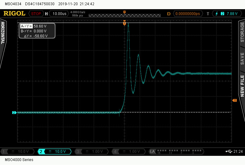
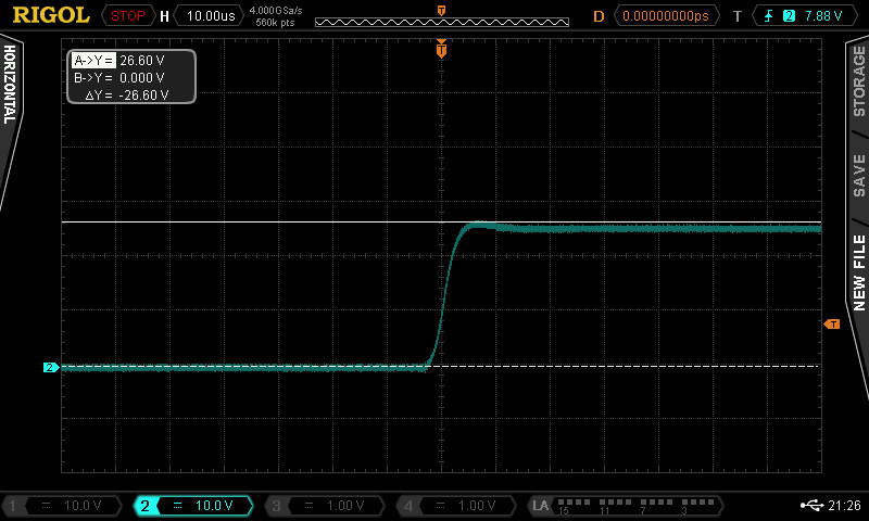
But whenever i hot plug the battery to circuit, BQ24610 and low side MOSFET gets burned in a very awful way. I searched the forum and couple of people also faced with this problem but there is no solution in the forum.
Since this is a battery application, this is a very unsafe circuit to use in project. I had three circuits and all got burned. I could not scope the PH, BTST, REGN and other pins. I am waiting new chips to arrive.
Is this a known issue? How can i fix this problem?
Hi Bera,
This is not a known issue regarding the IC, however as it is a charge controller, careful layout practices should be used. IC/MOSFET overheating is almost always a layout or schematic issue. Have you been able to test your solution on the EVM before beginning your design?The typical schematic is a good starting point, but for a fully verified solution, it is best to follow the schematic and layout shown in the user guide ().
thanks for reply,
I read other posts about this issue and as far as i understand, PH pin is used for battery detection.
It discharges battery for a short period of time on PH pin. But there is a disadvantage. It is a inductor-capacitor network.
I think it creates a very high voltage spike that it exceeds IC's absolute maximum ratings.
As soon as i get my new ICs, I will scope those pins and analyse.
Hi Bera,
No PH is not used for battery detection. This is the switching node of the buck converter circuit. The inductor and capacitor are part of the buck converter circuit as well. It is also useful to evaluate solution on EVM before starting design. For more information on battery detection you can refer to section 9.3.23 Battery Detection of datasheet and look at flowchart in figure 16. and plot in figure 17.
I am not quite sure I understand where you think your voltage spike is coming from. Once IC come in, let me know so I can propose some tests.
Hi Bera,
I will close the thread for tracking purposes. Once IC come back and you are able to perform tests, please re-open this thread.
Hi
I got my ICs.
I also bought TVS diode and new MOSFET which has higher voltage to experiment.
What would you recommend to test?
thanks
Hi everyone,
After couple of test and scoping, I found the solution.
Scope pictures shows the basic problem.
This picture shows what happens when hot-plug the battery.Voltage spike rise up to 60V an exceeds absolute maximum ratings and IC's get burned.
Thanks to ceramic capacitors, they can not filter this. I needed a bulk capacitor. So changed one ceramic capacitor with tantalum capacitor at the battery input.
This picture is the result. Voltage spikes are gone.
Datasheet (page 29, section 10.2.2.5) mentions input filter design for adapter input. But this type of filter design is needed at the battery input for protection.
This must be mentioned in datasheet. Battery input also requires filter design for hot-plug.
Hi Bera,
Do you have a long wire connection between your battery and BAT node? Inductance in between your battery and BAT node through wire or terminals could cause LC resonance that would result in a voltage ringing spike almost double. What is the voltage rating of your capacitors? If they are rated for low voltage, then derating can cause higher voltage ringing.
Care should be taken in designing system and setup for hot plug. We do not observe such results with battery hot plug on our EVM. Also BQ24610 employs battery absent detection to detect insertion of battery. In battery absent detection SRN is held at charge regulation voltage, and at every 500ms interval an 8mA discharge and 125mA charge current is applied to detect battery. This does not seem like an IC issue, but more like a setup issue.
The above scope capture if it is showing SRN is not correct, as I do not see battery absent before plug in. Please take a waveform when battery is absent, and when battery is inserted.
Hi
I did not buy EVM so I could not test with it.
After burning lots of ICs. I decided to remove everything step by step on the board and try with lower voltages.
I had battery packs 1S to 6S. So i tried with every combination.
I removed everything on board except ceramic capacitors at the battery input. IC, MOSFETs, inductor and other items were removed.
The voltage spike is there even only ceramic capacitors were placed. Voltage rating of those capacitors are 35V.
I tried with different cables also. 5cm to 30cm. They all showed same result. Voltage spike exist in every combination.
The pictures above is belong to empty circuit. IC were not placed when i measured. Only capacitors existed.
I designed my PCB with very short distances.
Adding one tantal capacitor helped with situation.
Hi Bera,
Initial test results mentioned IC gets burned, do you have a test result showing battery absent detection prior to insertion, and then triggering on the event of battery insertion?
Unfortunatly I dont have the saved results of battery detection.
I am going to try to capture with a scope.