A related question is a question created from another question. When the related question is created, it will be automatically linked to the original question.
If you have a related question, please click the "Ask a related question" button in the top right corner. The newly created question will be automatically linked to this question.
[FAQ] AM6442, AM6441, AM6422, AM6421, AM6412, AM6411 Custom board hardware design – Collaterals to Get started
Refer to the AM62Ax, AM62Px, AM62Dx LPDDR4 Board Design and Layout Guidelines
The DDR design guidelines outlines all details of power aware SI/PI simulations that need to be run. The eye mask checks from these power aware simulations are the signoff.
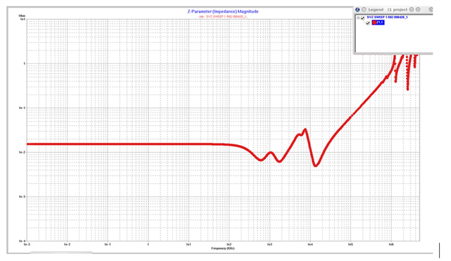
Power Distribution Networks: Implementation and Analysis
SitaraProcessor Power Distribution Networks: Implementation and Analysis
6.3.10 GPIO 6.3.10.1 MAIN Domain Table 6-35. GPIO0 Signal Descriptions
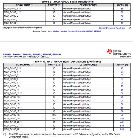
(1) This GPIO input signal has a debounce function. For more information on I/O Debounce configuration, see the TRM Device Configuration chapter.
6.3.10.2 MCU Domain Table 6-37. MCU_GPIO0 Signal Descriptions
TRM
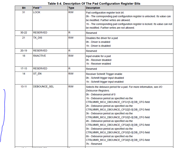
5.1.1.3.1.1 Pad Configuration Registers The pad configuration registers are used to configure most of the device pads. Each pad configuration register (PADMMR_PADCONFIG0 to PADMMR_PADCONFIG181) is assotiated only with one pad and has bits as described in Table 5-4.