Hi TI Experts,
I have the below queries regarding the crystal selection.
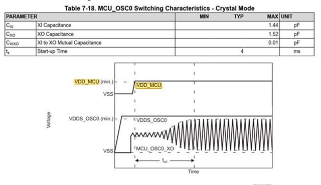
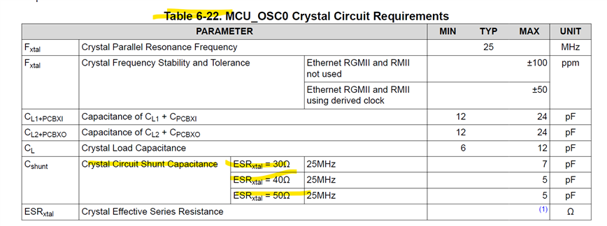
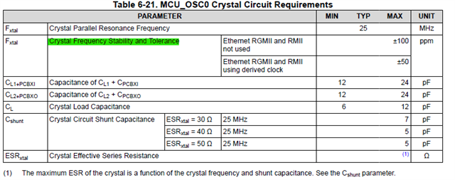
1. Recommended crystal frequency for MCU_OSC0
2. Do you have recommended part numbers for Crystal?
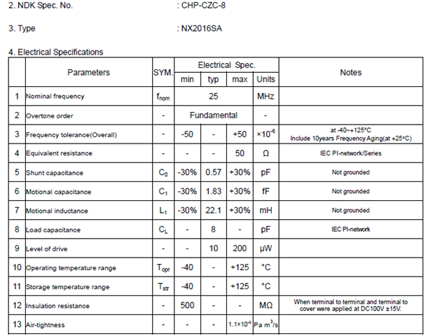
3. Can you help check if NX2016SA-25MHZ-EXS00A-CS10694, CRYSTAL 25.0000MHZ 8PF SMD could be used?
4. Do you have recommendations for MCU_OSC0 crystal selection.
5. Could you share the crystal part number used on the SK-AM62 and SK-AM62-LP?
6. Is it required to always connect the WKUP_LFOSC0?
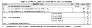
7. Do you have recommendations for WKUP_LFOSC0 crystal selection.
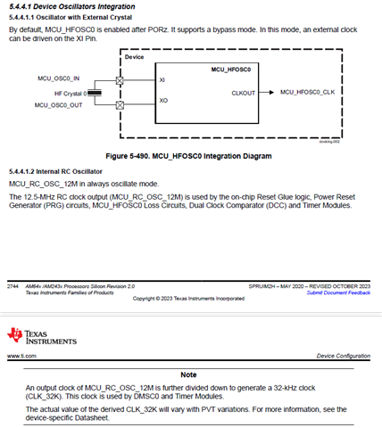
8. Can i use an oscillator as the clock source?
9. Is there a real max value for crystal ESR?
10. Is there some guidelines for the crystal circuit layout?
11. Is there a delay requirement for the MCU_PORz after all the power supplies ramp and does the delay depend on the clock source
12.Recommended value for Rbias and Rd R
13. MCU_OSC0_XI/MCU_OSC0_OUT starts before VDD_CORE voltage pull high, is this a concern
14. Does it have any side effect when MCU_OSC0_XI clock starts before VDD_CORE voltage pull high? What kind of conditions let MCU_OSC0_XI doesn't start until after VDD_CORE is applied?
15. I would like to check the specifications of the 32kHz XTAL connected to the AM62P.
The following are the specifications of the 25MHz XTAL.
Isn't there a specification for the tolerance range drawn by the green line in the 32kHz XTAL?
Let me know your thoughts.