This thread has been locked.

If you have a related question, please click the "Ask a related question" button in the top right corner. The newly created question will be automatically linked to this question.

TDA4AL-Q1: DDR1 pins

Part Number: TDA4AL-Q1

Hello TI experts,

It's about the DDR1 pins of TDA4AL-Q1.

Since the TDA4L-Q1 doesn't have DDR1 module, so what to do with these pins such as DDR1_DQS0P? Must pull or just left open?

Especially for J14 VDDA_0P8_PLL_DDR1 and J12 VDDS_DDR_C1.

Thanks a lot.
  • Hi,

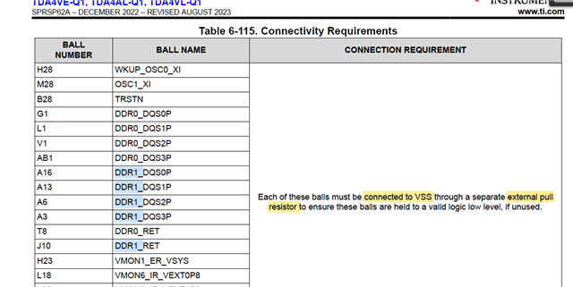
    Even though TDA4AL does not support the DDR1 sub-system, table 6-115 from the datasheet (SPRSP62A, revised August 2023) still applies.

    Especially for J14 VDDA_0P8_PLL_DDR1 and J12 VDDS_DDR_C1.

    I'll check to see if someone can comment on whether the above supplies are required. As several people are still out of office this week, please anticipate a delay in response.

    Regards,
    Kevin

  • Hello Kevin S,

    Thanks for your help.

    Besides, if the J14 VDDA_0P8_PLL_DDR1 and J12 VDDS_DDR_C1 are still needing supplied, please also help check how many caps are still required?

    Same as DDR0 or just connect to power supply?

    Thanks a lot.

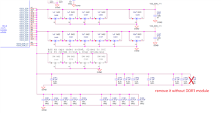
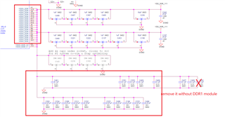
  • All power supplies are required to be supplied with correct voltage, regardless if peripheral is used or unused.  This should answer the question regarding VDDA_0P8_PLL_DDR! and VDDS_DDR_C1.  The decoupling capacitors are not required if the interfaces are unused (no activity thus no switching currents).

    Regarding the DDR1_DQS0P signal(s) - we recommend they be pulled down and the DDR1_DQS0N signal be pulled up.  The exact direction does not matter as long as they are pulled in OPPOSITE directions.

  • Hello Robert,

    I would like to confirm further information with you.

    For VDDA_0P8_PLL_DDR! and VDDS_DDR_C1

    1. If we don't use DDR1 module, can we remain the decoupling capacitors? For example, we use TDA4AL chips without DDR1 module.

    2. To remove the decoupling capacitors , could confirm if these capacitors can be removed?

    Just remove a 100nF cap for each pin?

  • Correct - power should still be applied to the pins but the LPDDR1 interface will not be operational, thus the decoupling is not required.  The highlighted caps can be removed.

  • Robert, thank you for your quick reply.

    By the way, I would like to confirm how should we put the decoupling capacitors for VDDS_DDR pins.

    If there is a 100n and 470n for every pin, it is clear to put them closed every pin. But the number of caps is not equal to the number of pins. So how should we put the caps? Maybe put one/two 100n and 470n caps for 2 or 3 near pins?

  • I recommend you review the layout/placement of the capacitors on the EVM and follow as closely as possible.  Design file are located here: www.ti.com/.../sprr439