PROCESSOR-SDK-AM64X: Issue to run TI's pcie_buf_transfer_rc example on core R5F

Part Number: PROCESSOR-SDK-AM64X
Other Parts Discussed in Thread: SYSCONFIG, AM625, TMDS64EVM

Tool/software:

Hello,

At the moment we are working on application that will run on r5f0 core whose objective is to configure the pcie as root complex and list the connected endpoints.

We are running the pcie_buf_transfer_rc example on the core provided on the sdk mcu_plus_sdk_am64x_08_05_00_24, however we are facing an issue in the middle of the of the Drivers_pcieOpen execution.
On the first local registers reading, when the command status register is read (Pcie_readStatusCmdReg), the application stops on line "val = swReg->raw = *hwReg_STATUS_COMMAND_REGISTER;"

// Location: Drivers_pcieOpen->Pcie_open->Pci_cfgRC

/* Enable memory access and mastership of the bus */
memset (&setRegs, 0, sizeof(setRegs));
memset (&getRegs, 0, sizeof(getRegs));

getRegs.statusCmd = &statusCmd;
status = Pcie_readRegs (handle, PCIE_LOCATION_LOCAL, &getRegs);

(...)


The hwReg_STATUS_COMMAND_REGISTER value is 0x0D000004. Is a value in this range expected?

Apart of this, two points to take in account:
1) I am not using ccs, we are integrating the source code in our build system, so we don't have the ccs debug setup.
2) I disabled pcie0_ep and pcie0_rc in dts file, to avoid any conflict with the pci kernel setup

Patch summary

(...)
arch/arm64/boot/dts/ti/k3-am642-evm.dts | 9 ++++++++-
(...)
 &pcie0_rc {
-	status = "okay";
+	status = "disabled";
 	reset-gpios = <&exp1 5 GPIO_ACTIVE_HIGH>;
 	phys = <&serdes0_pcie_link>;
 	phy-names = "pcie-phy";
 	num-lanes = <1>;
 };

+&pcie0_ep {
+	status = "disabled";
+	phys = <&serdes0_pcie_link>;
+	phy-names = "pcie-phy";
+	num-lanes = <1>;
+};
+
(...)

These changes were confirmed from Linux by executing the following commands. Both commands returned the disabled state:

cat /proc/device-tree/bus@<id>/pcie@<id>/status
cat /proc/device-tree/bus@<id>/pcie-ep@<id>/status


Based on this, any suggestions as to where the problem might be? If not, what do you suggest to find the solution?

References
Example : AM64x MCU+ SDK: PCIE buffer transfer RC (ti.com)

Best Regards

  •  
    I hope you're well.
    we are facing this issue, can you please help?

  • Hello Joao,

    Nick Saulnier is out of office this week, please ping this thread again if there hasn't been any response next week.

    -Daolin

  • Hello Joao,

    I'm not TI, but maybe I can help you a bit while you're waiting for Nick.

    2) I disabled pcie0_ep and pcie0_rc in dts file, to avoid any conflict with the pci kernel setup

    I take that to mean you're running the pcie_buf_transfer_rc parallel as a remoteproc application alongside of Linux?

    On the first local registers reading, when the command status register is read (Pcie_readStatusCmdReg), the application stops on line "val = swReg->raw = *hwReg_STATUS_COMMAND_REGISTER;"

    Could you elaborate what you mean by "the application stops"? Does it crash?

    The hwReg_STATUS_COMMAND_REGISTER value is 0x0D000004. Is a value in this range expected?

    That's the _address_ of this register being read, see TRM (Rev. D) page 7512. If it crashes (e.g. data abort) at that point my first guess is that the clock to the PCIe module isn't enabled. You said you're not using CCS. Are you also not using TI's SysConfig? Did you manually enable the clocks for the PCIe module?

    If you're indeed running Linux you could verify the clocking before/after starting your R5f application from Linux using TI's k3conf tool.

    Regards,

    Dominic

  • Hello Daolin,
    Thank you for the information.

  • Hello Dominic,

    Thank you for your answer.

    Answering your questions:

    I take that to mean you're running the pcie_buf_transfer_rc parallel as a remoteproc application alongside of Linux?

    A.1) Yes, I am running as remoteproc application.

    =======================================

    Could you elaborate what you mean by "the application stops"? Does it crash?

    A.2) As I'm running the application without using CCS, I don't have much information on this topic. I am simply using log messages to monitor the application's evolution and print the variables that I want to analyze. To see the log messages, I am consulting the r5f trace, for that, I am executing the command:

    cat /sys/kernel/debug/remoteproc/remoteproc1/trace0

    =======================================

    Are you also not using TI's SysConfig?

    A.3) No. I am using the following sysconfig file:

    /**
     * These arguments were used when this file was generated. They will be automatically applied on subsequent loads
     * via the GUI or CLI. Run CLI with '--help' for additional information on how to override these arguments.
     * @cliArgs --device "AM64x_beta" --package "ALV" --part "Default" --context "r5fss0-0" --product "MCU_PLUS_SDK_AM64x@08.05.00"
     * @versions {"tool":"1.14.0+2667"}
     */
    
    /**
     * Import the modules used in this configuration.
     */
    const ipc        = scripting.addModule("/drivers/ipc/ipc");
    const pcie       = scripting.addModule("/drivers/pcie/pcie", {}, false);
    const pcie1      = pcie.addInstance();
    const mpu_armv7  = scripting.addModule("/kernel/dpl/mpu_armv7", {}, false);
    const mpu_armv71 = mpu_armv7.addInstance();
    const mpu_armv72 = mpu_armv7.addInstance();
    const mpu_armv73 = mpu_armv7.addInstance();
    const mpu_armv74 = mpu_armv7.addInstance();
    const mpu_armv75 = mpu_armv7.addInstance();
    const mpu_armv76 = mpu_armv7.addInstance();
    const mpu_armv77 = mpu_armv7.addInstance();
    
    /**
     * Write custom configuration values to the imported modules.
     */
    ipc.enableLinuxIpc = true;
    
    pcie1.$name                = "CONFIG_PCIE0";
    pcie1.gen                  = "PCIE_GEN2";
    pcie1.ibAtu.create(1);
    pcie1.ibAtu[0].$name       = "IB_ATU_CFG0";
    pcie1.ibAtu[0].lowerBase   = "0x90000000";
    pcie1.ibAtu[0].externs     = "extern uint32_t dst_buf[];";
    pcie1.ibAtu[0].lowerTarget = "(uint32_t)dst_buf";
    pcie1.obAtu.create(1);
    pcie1.obAtu[0].$name       = "OB_ATU_CFG0";
    pcie1.obAtu[0].lowerBase   = "0x68000000UL + 0x01000000U";
    pcie1.obAtu[0].lowerTarget = "0x70000000";
    
    mpu_armv71.$name             = "CONFIG_MPU_REGION0";
    mpu_armv71.allowExecute      = false;
    mpu_armv71.attributes        = "Device";
    mpu_armv71.accessPermissions = "Supervisor RD+WR, User RD";
    mpu_armv71.size              = 31;
    
    mpu_armv72.$name             = "CONFIG_MPU_REGION1";
    mpu_armv72.size              = 15;
    mpu_armv72.accessPermissions = "Supervisor RD+WR, User RD";
    
    mpu_armv73.$name             = "CONFIG_MPU_REGION2";
    mpu_armv73.size              = 15;
    mpu_armv73.accessPermissions = "Supervisor RD+WR, User RD";
    mpu_armv73.baseAddr          = 0x41010000;
    
    mpu_armv74.$name             = "CONFIG_MPU_REGION3";
    mpu_armv74.baseAddr          = 0x70000000;
    mpu_armv74.accessPermissions = "Supervisor RD+WR, User RD";
    mpu_armv74.size              = 21;
    
    mpu_armv75.$name        = "CONFIG_MPU_REGION4";
    mpu_armv75.attributes   = "NonCached";
    mpu_armv75.allowExecute = false;
    mpu_armv75.size         = 16;
    mpu_armv75.baseAddr     = 0xA5000000;
    
    mpu_armv76.$name    = "CONFIG_MPU_REGION5";
    mpu_armv76.size     = 31;
    mpu_armv76.baseAddr = 0x80000000;
    
    mpu_armv77.$name        = "CONFIG_MPU_REGION6";
    mpu_armv77.size         = 20;
    mpu_armv77.baseAddr     = 0xA0000000;
    mpu_armv77.attributes   = "NonCached";
    mpu_armv77.allowExecute = false;
    

    =======================================

    Did you manually enable the clocks for the PCIe module?

    A.4) I am not aware of this process. I just configured SysConfig.
    During the configuration of the sysconfig file through the tool, in the pcie content, I did not find any field to configure the clocks.
    Where can I find more information on this topic?

    =======================================

    Best regards,
    Joao Lima

  • Hello Joao,

    A.2) As I'm running the application without using CCS,

    if you have a JTAG debugger (e.g. xds110 or xds200) I could show you how to debug an R5f application launched via remoteproc. Alterantively you could use OpenOCD. There's a talk by  explaining how to use OpenOCD running on A53 Linux to debug the R5f.

    A.4) I am not aware of this process. I just configured SysConfig.

    since you're using SysConfig I guess SysConfig should have generated the code to configure the clocks.

    You can have a look at the generated ti_power_clock_config.c. There's are two arrays gSocModules and gSocModulesClockFrequency that list all modules that will be configured and their frequencies.

    With Linux and MCU+ SDK / SysConfig you need to be careful about the R5f's configuration of module clocks conflicting with the Linux configuration. That's what I used k3conf for. It can dump the current settings of the clocks before launching the R5f and afterwards, and you can easily diff what got changed.

    Regards,

    Dominic

  • Hello Dominic,

    There's are two arrays gSocModules and gSocModulesClockFrequency that list all modules that will be configured and their frequencies.

    On the generated code, we are getting:

    uint32_t gSocModules[] = {
        TISCI_DEV_SERDES_10G0,
        TISCI_DEV_PCIE0,
    
        SOC_MODULES_END,
    };
    
    SOC_ModuleClockFrequency gSocModulesClockFrequency[] = {
    
        { SOC_MODULES_END, SOC_MODULES_END, SOC_MODULES_END },
    };

    Looks good for me.

    ===========================================

    how to use OpenOCD running on A53 Linux to debug the R5f

    Thank you for the suggestion. I will search.

    Meanwhile, I will install the k3conf and check the settings.
    Thank you.

  • Hello,

    I have not experimented with OpenOCD myself yet, so that might be a better fit for your debug than what I am about to suggest.

    Here are additional resources about debugging remote cores from Linux:
    https://dev.ti.com/tirex/explore/node?a=7qm9DIS__LATEST&node=A__AU9Punu4yTQu9hRP62aoug__AM64-ACADEMY__WI1KRXP__LATEST

    Other than that, Dominic's suggestions to verify that the PCIE peripheral is actually clocked are what I would suggest checking. I am going to reassign your thread to a team member more familiar with MCU+ PCIE to see if they have any further insights.

    Regards,

    Nick

  • Hi,

    I have not experimented with OpenOCD myself yet, so that might be a better fit for your debug than what I am about to suggest.

    If you've got access to JTAG pins and a XDC1xx/2xx  / are using an EVM with on-board XDC: Use that with CCS

    If you can't use a JTAG debugger: Use OpenOCD locally on the AM64x Linux

    Regards,

    Dominic

  • Hello Nick, 

    I am already following the techniques described in the link you shared. Thanks.

    Meanwhile, I followed 's suggestion.

    I have some questions about checking the pcie clock.

    1. Do I have to have a peripheral PCIe connected to our root complex?
      1. According to what you can see in the code I published in the ticket, the unexpected behavior is happening in the Pci_cfgRC function. In other words, in my opinion we are still in a local context, where the first reading of the status command register fails.
      2. However, I already have a setup with a standard peripheral and the error persists.
    2. From what I analyzed of the k3conf logs, everything appears to be well configured. However, I publish the logs I had for analysis.
    3. When I run the command 'k3conf dump device | grep R5F', some processors have the DEVICE_STATE_OFF state, however I can load the application for one of these cores, r5f0_0, and consult its log successfully. This brings me to the question of the meaning and functionality of the DEVICE_STATE_OFF tag. What is this tag for?

    Thank you.

    Regards,
    Joao

    root@am64xx-evm:~# k3conf dump clock | grep -E 'PCI | R5F'
    |-------------------------------------------------------------------------------------------------------------------------------------------|
    | Device ID | Clock ID | Clock Name                                                                     | Status          | Clock Frequency |
    |-------------------------------------------------------------------------------------------------------------------------------------------|
    |   114     |     0    | DEV_PCIE0_PCIE_CBA_CLK                                                         | CLK_STATE_READY | 250000000       |
    |   114     |     1    | DEV_PCIE0_PCIE_CPTS_RCLK_CLK                                                   | CLK_STATE_READY | 225000000       |
    |   114     |     2    | DEV_PCIE0_PCIE_CPTS_RCLK_CLK_PARENT_POSTDIV4_16FF_MAIN_2_HSDIVOUT5_CLK         | CLK_STATE_READY | 225000000       |
    |   114     |     3    | DEV_PCIE0_PCIE_CPTS_RCLK_CLK_PARENT_POSTDIV4_16FF_MAIN_0_HSDIVOUT6_CLK         | CLK_STATE_READY | 200000000       |
    |   114     |     4    | DEV_PCIE0_PCIE_CPTS_RCLK_CLK_PARENT_BOARD_0_CP_GEMAC_CPTS0_RFT_CLK_OUT         | CLK_STATE_READY | 0               |
    |   114     |     5    | DEV_PCIE0_PCIE_CPTS_RCLK_CLK_PARENT_BOARD_0_CPTS0_RFT_CLK_OUT                  | CLK_STATE_READY | 0               |
    |   114     |     6    | DEV_PCIE0_PCIE_CPTS_RCLK_CLK_PARENT_BOARD_0_MCU_EXT_REFCLK0_OUT                | CLK_STATE_READY | 0               |
    |   114     |     7    | DEV_PCIE0_PCIE_CPTS_RCLK_CLK_PARENT_BOARD_0_EXT_REFCLK1_OUT                    | CLK_STATE_READY | 0               |
    |   114     |     8    | DEV_PCIE0_PCIE_CPTS_RCLK_CLK_PARENT_WIZ16B2M4CT_MAIN_0_IP1_LN0_TXMCLK          | CLK_STATE_READY | 0               |
    |   114     |     9    | DEV_PCIE0_PCIE_CPTS_RCLK_CLK_PARENT_K3_PLL_CTRL_WRAP_MAIN_0_CHIP_DIV1_CLK_CLK  | (null)          | 0               |
    |   114     |    10    | DEV_PCIE0_PCIE_LANE0_REFCLK                                                    | CLK_STATE_READY | 0               |
    |   114     |    11    | DEV_PCIE0_PCIE_LANE0_RXCLK                                                     | CLK_STATE_READY | 0               |
    |   114     |    12    | DEV_PCIE0_PCIE_LANE0_RXFCLK                                                    | CLK_STATE_READY | 0               |
    |   114     |    13    | DEV_PCIE0_PCIE_LANE0_TXFCLK                                                    | CLK_STATE_READY | 0               |
    |   114     |    14    | DEV_PCIE0_PCIE_LANE0_TXMCLK                                                    | CLK_STATE_READY | 0               |
    |   114     |    15    | DEV_PCIE0_PCIE_PM_CLK                                                          | CLK_STATE_READY | 12500000        |
    |   114     |    16    | DEV_PCIE0_PCIE_LANE0_TXCLK                                                     | CLK_STATE_READY | 0               |
    |   121     |     0    | DEV_R5FSS0_CORE0_CPU_CLK                                                       | CLK_STATE_READY | 800000000       |
    |   121     |     1    | DEV_R5FSS0_CORE0_INTERFACE_CLK                                                 | CLK_STATE_READY | 800000000       |
    |   122     |     0    | DEV_R5FSS0_CORE1_CPU_CLK                                                       | CLK_STATE_READY | 800000000       |
    |   122     |     1    | DEV_R5FSS0_CORE1_INTERFACE_CLK                                                 | CLK_STATE_READY | 800000000       |
    |   123     |     0    | DEV_R5FSS1_CORE0_CPU_CLK                                                       | CLK_STATE_READY | 800000000       |
    |   123     |     1    | DEV_R5FSS1_CORE0_INTERFACE_CLK                                                 | CLK_STATE_READY | 800000000       |
    |   124     |     0    | DEV_R5FSS1_CORE1_CPU_CLK                                                       | CLK_STATE_READY | 800000000       |
    |   124     |     1    | DEV_R5FSS1_CORE1_INTERFACE_CLK                                                 | CLK_STATE_READY | 800000000       |
    
    
    root@am64xx-evm:~# k3conf show clock | grep -E 'PCI | R5F'
    |-----------------------------------------------------------------------------------------------------------------------------------------------------------------|
    | Device ID | Clock ID | Clock Name                                                                                           | Status          | Clock Frequency |
    |-----------------------------------------------------------------------------------------------------------------------------------------------------------------|
    ...
    |   114     |     0    | DEV_PCIE0_PCIE_CBA_CLK                                                          | Input clock                                                |
    |   114     |     1    | DEV_PCIE0_PCIE_CPTS_RCLK_CLK                                                    | Input muxed clock                                          |
    |   114     |     2    | DEV_PCIE0_PCIE_CPTS_RCLK_CLK_PARENT_POSTDIV4_16FF_MAIN_2_HSDIVOUT5_CLK          | Parent input clock option to DEV_PCIE0_PCIE_CPTS_RCLK_CLK  |
    |   114     |     3    | DEV_PCIE0_PCIE_CPTS_RCLK_CLK_PARENT_POSTDIV4_16FF_MAIN_0_HSDIVOUT6_CLK          | Parent input clock option to DEV_PCIE0_PCIE_CPTS_RCLK_CLK  |
    |   114     |     4    | DEV_PCIE0_PCIE_CPTS_RCLK_CLK_PARENT_BOARD_0_CP_GEMAC_CPTS0_RFT_CLK_OUT          | Parent input clock option to DEV_PCIE0_PCIE_CPTS_RCLK_CLK  |
    |   114     |     5    | DEV_PCIE0_PCIE_CPTS_RCLK_CLK_PARENT_BOARD_0_CPTS0_RFT_CLK_OUT                   | Parent input clock option to DEV_PCIE0_PCIE_CPTS_RCLK_CLK  |
    |   114     |     6    | DEV_PCIE0_PCIE_CPTS_RCLK_CLK_PARENT_BOARD_0_MCU_EXT_REFCLK0_OUT                 | Parent input clock option to DEV_PCIE0_PCIE_CPTS_RCLK_CLK  |
    |   114     |     7    | DEV_PCIE0_PCIE_CPTS_RCLK_CLK_PARENT_BOARD_0_EXT_REFCLK1_OUT                     | Parent input clock option to DEV_PCIE0_PCIE_CPTS_RCLK_CLK  |
    |   114     |     8    | DEV_PCIE0_PCIE_CPTS_RCLK_CLK_PARENT_WIZ16B2M4CT_MAIN_0_IP1_LN0_TXMCLK           | Parent input clock option to DEV_PCIE0_PCIE_CPTS_RCLK_CLK  |
    |   114     |     9    | DEV_PCIE0_PCIE_CPTS_RCLK_CLK_PARENT_K3_PLL_CTRL_WRAP_MAIN_0_CHIP_DIV1_CLK_CLK   | Parent input clock option to DEV_PCIE0_PCIE_CPTS_RCLK_CLK  |
    |   114     |    10    | DEV_PCIE0_PCIE_LANE0_REFCLK                                                     | Input clock                                                |
    |   114     |    11    | DEV_PCIE0_PCIE_LANE0_RXCLK                                                      | Input clock                                                |
    |   114     |    12    | DEV_PCIE0_PCIE_LANE0_RXFCLK                                                     | Input clock                                                |
    |   114     |    13    | DEV_PCIE0_PCIE_LANE0_TXFCLK                                                     | Input clock                                                |
    |   114     |    14    | DEV_PCIE0_PCIE_LANE0_TXMCLK                                                     | Input clock                                                |
    |   114     |    15    | DEV_PCIE0_PCIE_PM_CLK                                                           | Input clock                                                |
    |   114     |    16    | DEV_PCIE0_PCIE_LANE0_TXCLK                                                      | Output clock                                               |
    |   121     |     0    | DEV_R5FSS0_CORE0_CPU_CLK                                                        | Input clock                                                |
    |   121     |     1    | DEV_R5FSS0_CORE0_INTERFACE_CLK                                                  | Input clock                                                |
    |   122     |     0    | DEV_R5FSS0_CORE1_CPU_CLK                                                        | Input clock                                                |
    |   122     |     1    | DEV_R5FSS0_CORE1_INTERFACE_CLK                                                  | Input clock                                                |
    |   123     |     0    | DEV_R5FSS1_CORE0_CPU_CLK                                                        | Input clock                                                |
    |   123     |     1    | DEV_R5FSS1_CORE0_INTERFACE_CLK                                                  | Input clock                                                |
    |   124     |     0    | DEV_R5FSS1_CORE1_CPU_CLK                                                        | Input clock                                                |
    |   124     |     1    | DEV_R5FSS1_CORE1_INTERFACE_CLK                                                  | Input clock                                                |
    
    
    root@am64xx-evm:~# k3conf show processor
    |---------------------------------------------|
    | Device ID | Processor ID | Processor Name   |
    |---------------------------------------------|
    |   135     |      32      | A53SS0_CORE_0    |
    |   136     |      33      | A53SS0_CORE_1    |
    |     9     |      24      | MCU_M4FSS0_CORE0 |
    |   121     |       1      | R5FSS0_CORE0     |
    |   122     |       2      | R5FSS0_CORE1     |
    |   123     |       6      | R5FSS1_CORE0     |
    |   124     |       7      | R5FSS1_CORE1     |
    |---------------------------------------------|
    
    root@am64xx-evm:~# k3conf dump device 114
    |------------------------------------------------|
    | Device ID | Device Name      | Device Status   |
    |------------------------------------------------|
    |   114     | AM64X_DEV_PCIE0  | DEVICE_STATE_ON |
    |------------------------------------------------|
    
    root@am64xx-evm:~# k3conf dump device | grep R5F
    |   119     | AM64X_DEV_R5FSS0                     | DEVICE_STATE_ON  |
    |   120     | AM64X_DEV_R5FSS1                     | DEVICE_STATE_ON  |
    |   121     | AM64X_DEV_R5FSS0_CORE0               | DEVICE_STATE_OFF |
    |   122     | AM64X_DEV_R5FSS0_CORE1               | DEVICE_STATE_OFF |
    |   123     | AM64X_DEV_R5FSS1_CORE0               | DEVICE_STATE_OFF |
    |   124     | AM64X_DEV_R5FSS1_CORE1               | DEVICE_STATE_OFF |

  • Hello Joao,

    if your application crashes when accessing the status register it is the PCIe core clock that's the problem. The core clock should be DEV_PCIE0_PCIE_LANE0_TXMCLK, which is shown as 0 above. I'm not sure if k3conf "knows" all the possible sources for this clock, i.e. if 0 means it really is 0, or if k3conf just doesn't know where that clock comes from.

    In the hardware, this clock comes from the SerDes, see page 7487 in the TRM (Rev. H). That clock can be generated internally, and output on the RefClk pins, or it can be input on those pins.

    The PCIe driver in version 08.05 assumes that this clock is generated internally, and is output on the RefClk pins, see "source\drivers\pcie\v0\soc\am64x_am243x\pcie_serdes.c". See page 8087 for the sources that can drive the internal reference clock.

    -> check if you can see how the SerDes is being clocked (https://downloads.ti.com/tisci/esd/latest/5_soc_doc/am64x/clocks.html#clocks-for-serdes-10g0-device)

    Best Regards,

    Dominic

  • Thanks for the response Dominic.

    Today, I received a second board to test and debug the PCI demo application available by TI. But I will give updates about this topic in the next days.

    Meanwhile, I was analyzing a debug setup to use OpenOCD. For this, as you suggested, I followed the talk by  explaining how to use OpenOCD running on A53 Linux to debug the R5F, and everything appears to be working as expected.

    However, I am having some problems when debugging through openocd with dmem. Using gdb-multiarch for remote debugging on an r5f 0 core, the gdb application does not stop at certain breakpoints and the local variables in the gdb dashboard do not conform to the expected values. However, on the board, when I run the cat trace of r5f 0, using the command 'cat /sys/kernel/debug/remoteproc/remoteproc0/trace0', the values ​​are correct. The code that I am using is very simple, is printing a variable value in a for loop.

    To support the debug with dmem for the am64x, I updated some files to be used with openocd (+info: github.com/.../ti-am64x-openocd).
    One of the files was the ti_k3.cfg, in which I added the memory region values ​​for the am642 platform to use dmem.

    Analyzing the values ​​configured for am625, I confirmed in the technical reference manual of am625 and am642 that the _dmem_base_address and _dmem_emu_base_address values ​​are the same in both cases, the values ​​correspond to the DEBUGSS_WRAP0_CFGAP1 and DEBUGSS_WRAP0_ROM_TABLE_1_1 memory region. For the remaining values, after a code analysis, I considered the same values for both platforms (+info: github.com/.../ti_k3.cfg

    set _dmem_base_address 0x740002000
    set _dmem_ap_address_offset 0x100
    set _dmem_max_aps 10
    # Emulated AP description
    set _dmem_emu_base_address 0x760000000
    set _dmem_emu_base_address_map_to 0x1d500000
    set _dmem_emu_ap_list 1

    To ensure we have all the symbols, I added the compilation flags to our compilation process:
    '-O0 -ggdb'

    So, based on the strange behavior I'm having with gdb and the dmem configuration I've made, do you have any suggestions as to what might be happening?

    Openocd version
    root@am64xx-evm:/lib/firmware# openocd -v
    Open On-Chip Debugger 0.12.0+dev-00616-gc5358c84a-dirty (2024-06-18-14:06)
    Licensed under GNU GPL v2

    Gdb-multiarch version
    GNU gdb (GDB) Fedora Linux 14.1-3.fc38

    Compiler version
    ti-cgt-armllvm_3.2.1.LTS

    Sdk version
    mcu_plus_sdk_am64x_09_02_01_05

  • Another issue that we are facing is about the graceful stop of the r5f. 

    When I stop the core r5f 0 and relaunch the firmware, the board crashes. Only with a power cycle will the board work again.
    Any suggestions about why this is happening?

    Compiler version
    ti-cgt-armllvm_3.2.1.LTS

    Sdk version
    mcu_plus_sdk_am64x_09_02_01_05

    Thanks.

    Best Regard,
    Joao Lima

  • Hello Joao,

    basically that should work. Breakpoints were no problem for me. I had an issue with single stepping, but that worked after adding a "maskisr on" (single stepping otherwise fails because an IRQ causes the CPU to resume elsewhere, or so it seemed). Reading memory wasn't a problem at all.

    Your changes to ti_k3.cfg appear to be fine, I remember adding similar code.

    Not sure if this forum is appropriate to discuss OpenOCD issues. You might want to try OpenOCD's IRC channel or mailing list.

    Graceful stop is rather new I think. From what I know it should work, but as I understand it this requires a clean shutdown of your firmware. Might be best to have a separate thread for that issue.

    If you have further questions regarding PCIe feel free to post here, I'll try to help.

    Regards,

    Dominic

  • Hello Joao,

    Please create a separate thread for graceful stop of the R5F and ask for me. I've got one more day before vacation where I can comment.

    Assuming you are using Linux to shut down and restart the R5F core, please start by referring to the AM64x academy, multicore module, page "Graceful shutdown": https://dev.ti.com/tirex/explore/node?a=7qm9DIS__LATEST&node=A__AVt2qZLTY3BgKr3D4YIv8w__AM64-ACADEMY__WI1KRXP__LATEST

    Regards,

    Nick

  • Hello Nick,

    Thanks for your answer. I will consult them.

    I created a new ticket about this topic.
    (+) PROCESSOR-SDK-AM64X: R5F Graceful shutdown issue - Processors forum - Processors - TI E2E support forums

    Best regards,
    Joao Lima

  • Hello Dominic,

    Thank you for your answer. For openocd and gdb I will jump to the appropriate discussion channels.

    About Pcie, I already have more information about the pcie setup with two am64x boards, in which one r5f on one board runs firmware for pcie root complex and the other r5f on the second board as pcie endpoint.

    To overcome the initial problem reported, the command status register reading error, I changed the number of phy instances in file pcie_serdes.c (located at (...)/ti-am64xx/mcu_plus_sdk_am64x_09_02_01_05/source/drivers/pcie/v0/soc/am64x_am243x/):

    (...)
    int32_t Pcie_serdesInit(Pcie_Handle handle, uint32_t deviceNum)
    {
    (...)
    serdesLaneEnableParams.pcieGenType = pcieGen;
    serdesLaneEnableParams.operatingMode = CSL_SERDES_FUNCTIONAL_MODE;
    - serdesLaneEnableParams.phyInstanceNum = 0;
    + serdesLaneEnableParams.phyInstanceNum = 1;
    (...)


    And this resolved the local reading error of command status register. Now, I have the root complex firmware stucked on the loop inside of Pcie_checkLinkParams (loacted at pcie_v0.c). About the endpoint, it seems to have gone well, since I had a linkup.
    While I do more debugging, do you suggest anything about this topic?

    For better debugging and awareness of the system, regarding the firmwares I'm running, the functions to set the configuration as root complex and as endpoint are called from a freertos task. The code of both functions are the same ones that are available on sdk. In addiction, for future newcomers, each pcie rule has a distinct sysconfig, one to configure r5f as a root complex and another sysconfig to configure r5f as an endpoint.

    More useful information:

    1. I am first turning on the root complex board to wait for a linkup and then I turned on the second board, the endpoint board.
    2. Have the correct configuration of jumpers j34 and j35, according to the manual https://www.ti.com/lit/ug/spruj63a/spruj63a.pdf?ts=1719346858219&ref_url=https%253A%252F%252Fwww.ti.com%252Ftool%252FTMDS243EV .In my case, I had to remove the j34 jumper from the endpoint board, so that it does not suffer a reset from root complex.

    Thank you.

    Best regards,
    Joao Lima

  • Hello Joao,

    About Pcie, I already have more information about the pcie setup with two am64x boards, in which one r5f on one board runs firmware for pcie root complex and the other r5f on the second board as pcie endpoint.

    You should be able to use CCS to debug the R5f on these boards. There's an on-board xds110, and no need for using OpenOCD.

    To overcome the initial problem reported, the command status register reading error, I changed the number of phy instances in file pcie_serdes.c (located at (...)/ti-am64xx/mcu_plus_sdk_am64x_09_02_01_05/source/drivers/pcie/v0/soc/am64x_am243x/):

    That shouldn't be necessary. The AM64x has only a single SerDes instance.

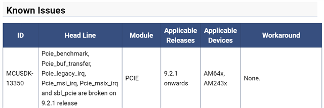
    Which of the existing examples have you tried? Please note that the release notes for version 09_02_01_05 mention that most of the examples are broken. I believe that pcie_msi_irq should actually be working, as that has already been adapted to the improved PCIe EP driver that is included in 09.02.01.05.

    To verify your setup it might help if you used two unmodified EVMs and a PCIe cable as described in the MCU+ SDK documentation (RefClk disconnected). Boot both boards with a sbl-null bootloader, and launch the application via CCS.

    That should just work as it is, without any modifications.

    With 09.02.01.05 I would expect only the following two examples to work:

    • pcie_enumerate_ep (connect the AM64x to an x86 running Linux or Windows, requires board modifications and cable with RefClk connected)
    • pcie_msi_irq_ep/rc (connect two AM64x to each other, requires stock board (no mods), and cable without RefClk connection)

    With 09.02.00.50 there is no pcie_enumerate_ep example, but all the other examples should work (connect two AM64x to each other, requires stock board (no mods), and cable without RefClk connection).

    Regards,

    Dominic

  • Hello Dominic,

    Thanks for the answer and the tips. Meanwhile, since your last answer, we have been analyzing and setting up a loopback setup with debugging via CCS.

    Which of the existing examples have you tried? Please note that the release notes for version 09_02_01_05 mention that most of the examples are broken. I believe that pcie_msi_irq should actually be working, as that has already been adapted to the improved PCIe EP driver that is included in 09.02.01.05.

    Thanks for the alert. I hadn't noticed that. Meanwhile, I have already reverted to mcu sdk 8.5.0.24 and setup CCS to debug both boards.

    You should be able to use CCS to debug the R5f on these boards. There's an on-board xds110, and no need for using OpenOCD.

    Yes. We are working with two am64xx revision PROC101-004 C without any modifications and the cable that we are using for a loopback setup with two boards has the ref. clocks disconnected.

    About the code, we are using the legacy IRQ example + FreeRTOS and are experiencing unexpected behavior.
    When we used the CCS connected to both boards and went through the code step by step with the help of the debugger, we were able to execute the main function to the end on both sides without any problems. For that, I am stepping over the open driver on one board and then on another board and repeat the process for all interrelated functions and sets of codes in order to synchronize them.

    However, if I run both applications on both sides without any synchronization between functions of the same logic, the programs do not run until the end.
    The result I'm getting from this last scenario is that the root complex code, when it is executed Pcie_readVendorDevId, the code breaks on reading the contents of the pointer on the line "val = swReg->raw = *hwReg_VENDOR_ID_DEV_ID;"
    At this point, we are in the context of reading endpoint identification data, and not in domain of supported pcie interruptions (legacy, msi, msix). Therefore, the example in study "is not very relevant" since the three existing examples for each type of interruption have the same initial code.

    Any comments regarding this behavior?

    Best regards,
    Joao Lima

  • Hello Dominic,

    I am witnessing another event related to PCIe speed configuration.

    When I configure my link speed as Gen1 in sysconfig, during the execution of our code, more precisely the pcie_open function of SDK 8.5, the Pcie_checkLinkParams function gets stuck in the loop since the configured/expected speed is gen1, but the available speed is gen2. is it expected?

    Another question, about the issue of this thread in general.
    Is it possible for you or someone from IT to set up the same setup using the SDK 8.5 example to confirm that the examples are working correctly?

    Thanks.
    Best regards,
    Joao Lima

  • Hello Joao,

    When I configure my link speed as Gen1 in sysconfig, during the execution of our code, more precisely the pcie_open function of SDK 8.5, the Pcie_checkLinkParams function gets stuck in the loop since the configured/expected speed is gen1, but the available speed is gen2. is it expected?

    that is a known issue in all versions <= 09.02.00. Up to that version the driver assumed that a link /must/ be established at that speed, and it would wait for that speed to be negotiated (i.e. possibly forever), but it didn't actually limit what it would negotiate. See this thread for a work around to actually limit the speed: e2e.ti.com/.../am2434-question-about-am2434-pcie

    In version 09.02.01, the link gen setting is used to limit what the local PCIe is able to negotiate. The driver merely reports what speed was negotiated, and the application needs to decide if that is "good enough". With the new driver if you set your speed to Gen1 it will be limited to Gen1, and you will get a Gen1 link. If you set the speed to Gen2 you could get a Gen2 OR a Gen1 link, depending on how the other end behaves.

    Another question, about the issue of this thread in general.
    Is it possible for you or someone from IT to set up the same setup using the SDK 8.5 example to confirm that the examples are working correctly?

    I know the examples used to work in 08.05/08.06/09.00. I remember having issues with the order of EP vs. RC startup, and the examples might be racy, but basically they work. I'll try to test this again the next couple of days. Maybe someone from TI can give you guidance before that.

    Regards,

    Dominic

  • Hello Dominic,

    that is a known issue in all versions <= 09.02.00. Up to that version the driver assumed that a link /must/ be established at that speed, and it would wait for that speed to be negotiated (i.e. possibly forever), but it didn't actually limit what it would negotiate. See this thread for a work around to actually limit the speed: e2e.ti.com/.../am2434-question-about-am2434-pcie

    Thank you for the clarification. I will check that.

    I know the examples used to work in 08.05/08.06/09.00. I remember having issues with the order of EP vs. RC startup, and the examples might be racy, but basically they work. I'll try to test this again the next couple of days. Maybe someone from TI can give you guidance before that.

    Ok. Deal. I will wait by your feedback about your setup. Meanwhile, I will check everything again.

    Thank you.

    Best regards, 
    Joao Lima

  • Hello ,

    Can you help with what is being discussed here?

    Best regards, 
    Joao Lima

  • Hi Jao,

    As mentioned in Release notes, we have some known issues with PCIe working examples in SDK.

    Did you get chance to check on your side?

    Regards

    Ashwani

  • Hello ,

    Thanks for the alert. I hadn't noticed that. Meanwhile, I have already reverted to mcu sdk 8.5.0.24 and setup CCS to debug both boards.

    Thanks for the alert, but in the meanwhile I'm already using SDK 8.5. and this has no indication of problems with the pcie examples, as we can confirm in AM64x MCU+ SDK: Release Notes 08.05.00 (ti.com)

    Do you suggest something else?

    Best regards, 
    Joao Lima

  • Oh, Thanks for pointing out part of conversation, I missed.

    We are working on this to try on our side.

    It may take some more time.

    Thanks for having patience.

    Regards

    Ashwani

  • No problem. I should have highlighted the sdk version too.

    Thank you. Let me know when you have news about.

    Best regards, 
    Joao Lima

  • Hello Joao,

    I've been able to successfully run the pcie_msi_irq_ep/rc examples from MCU+ SDK 08.05.00.24.

    • Both boards connected via the PCIe cable mentioned in the MCU+ SDK documentation, no RefClk connection
    • Both boards unmodified with regard to RefClk (i.e. both used their on-board clock generator as a separate reference)
    • I've booted both boards from SD card with the sbl_null bootloader
    • I've attached two instances of CCS to RC and EP
    • I've loaded the MAIN_Cortex_R5_0_0 with the RC and EP application, tested both Debug and Release
    • I let one of them run first, then the other. Order didn't matter.

    On the EP, I got this output:

    Device in EP mode

    On the RC, I got this output:

    Device in RC mode
    Endpoint Device ID: 100X
    Endpoint Vendor ID: 17CDX
    All tests have passed!!

    Afterwards both RC and EP were halted in abort() because they exited their main thread, this is expected.

    Maybe you could a) try to follow these steps as closely as possible or b) tell me what you did when you ran into problems.

    Regards,

    Dominic

  • Hello Dominic,

    Thank you for your answer.

    We aligned our setup configuration with what you described and the example worked.
    Booting both boards from the SD card with the sbl_null bootloader made the difference:
    https://software-dl.ti.com/mcu-plus-sdk/esd/AM64X/08_05_00_24/exports/docs/api_guide_am64x/EVM_SETUP_PAGE.html#EVM_SOC_INIT_SD_BOOT_MODE

    With this result in mind, we move on to the analysis of running the example binaries on the official wic image made available by TI.
    This analysis is composed of two test cases:
    Test 1) Use the binaries generated by the CCS.
    Test 2) Use the binaries generated by our build system.

    In test 1, both applications do not start on either card. The error we are getting is the following:

    [ 33.213916] remoteproc remoteproc0: powering up 78000000.r5f
    [ 33.221295] remoteproc remoteproc0: Booting fw image am64-main-r5f0_0-fw, size 742352
    [ 33.230445] remoteproc remoteproc0: bad phdr da 0x70080000 mem 0x12000
    [ 33.237170] remoteproc remoteproc0: Failed to load program segments: -22
    [ 33.244911] remoteproc remoteproc0: Boot failed: -22

    While in test 2, applications start but get stuck at Drivers_open. Behavior already reported before.
    The result of this analysis is the same for the image we are generating and using.

    Another approach we took was to remove from the dts any reference to serdes and pcie to approximate the characteristics of the sbl_null bootloader and to ensure that there is no configuration in relation to pcie.
    The changed files were:
    * arch/arm/dts/k3-am642-sk-u-boot.dtsi
    * arch/arm/dts/k3-am642-sk.dts
    * arch/arm/dts/k3-am642-evm.dts
    * arch/arm/dts/k3-am64-main.dtsi
    * arch/arm/dts/k3-am642-r5-sk.dts
    * arch/arm64/boot/dts/ti/k3-am642-evm.dts

    But the result is the same for each test case.


    Any suggestions for running applications on an operating system image?

    Best regards,
    Joao Lima

  • Hello Joao,

    the error you're getting on test 1 is a generic remoteproc issue, not related to PCIe.

    Apparently your linker script loads some sections to MSRAM at 7008000, but your devicetree doesn't assign that memory to the R5f. Add reserved memory to the dts, or change your linker script to use the memory  already assigned to the r5f.

    Regarding test 2:

    I'd like to understand how you were running the application before you switched to SBL null, and if that was the same error you're seeing now linux?

    Regards, 

    Dominic

  • Hello Dominic,

    the error you're getting on test 1 is a generic remoteproc issue, not related to PCIe.

    Apparently your linker script loads some sections to MSRAM at 7008000, but your devicetree doesn't assign that memory to the R5f. Add reserved memory to the dts, or change your linker script to use the memory  already assigned to the r5f.

    I know. Thanks. But I was waiting for the example to work the first time. But apart from that, are the examples expected to work in the official TI image?

    I'd like to understand how you were running the application before you switched to SBL null, and if that was the same error you're seeing now linux?

    The question was not clear to me. Can you rephrase please?

    Nowadays I'm flashing an image that we generate for the emmc of our boards and then we initialize the applications on the R5F via remoteproc commands.

    Regards,
    Joao Lima

  • I know. Thanks. But I was waiting for the example to work the first time. But apart from that, are the examples expected to work in the official TI image?

    No. I believe none of the examples (except the Linux IPC example) are expected to work as-is via remoteproc. Someone form TI should comment on that.

    The question was not clear to me. Can you rephrase please?

    Before you switched to the null bootloader it didn't work. I wanted to understand what you did before,  to maybe understand what issues you're seeing now with Linux and remoteproc. 

    And I wanted to understand if the problem now in "test 2" was similar to before. 

    How did you boot the boards before null bootloader?

    Regards, Dominic 

  • Hello Dominic,

    No. I believe none of the examples (except the Linux IPC example) are expected to work as-is via remoteproc. Someone form TI should comment on that.

    Ok. Let's wait by the TI team confirmation.

    And I wanted to understand if the problem now in "test 2" was similar to before. 

    About the test 2, the behavior is the same as the scenario of when we use the image that we generate.

    In other words, regardless of whether I use the IT image or the image we generate ourselves, the applications are stuck. Both in Pcie_waitLinkUp function.

    I'm booting in mmc on both boards to boot the image I have saved in emmc.

    Best regards,
    Joao Lima

  • Hello Joao,

    About the test 2, the behavior is the same as the scenario of when we use the image that we generate.

    In other words, regardless of whether I use the IT image or the image we generate ourselves, the applications are stuck. Both in Pcie_waitLinkUp function.

    I'm booting in mmc on both boards to boot the image I have saved in emmc.
    • Is the hardware setup exactly the same as before, when you had success with the null SBL and pcie_msi_irq_ep/rc?
    • Are you running Linux on both RC and EP?
    • Are you running MCU+ SDK based PCIe EP on RC and EP?
    • Did you disable PCIe in Linux on RC and EP?

    I'm not sure what you're refering to when say

    While in test 2, applications start but get stuck at Drivers_open. Behavior already reported before.

    Initially you had an issue that

    the application stops on line "val = swReg->raw = *hwReg_STATUS_COMMAND_REGISTER;"

    At some point your issue was that

    firmware stucked on the loop inside of Pcie_checkLinkParams

    Now you're stuck in Pcie_waitLinkUp. That seems to be a new problem.

    Regards,

    Dominic

    • Is the hardware setup exactly the same as before, when you had success with the null SBL and pcie_msi_irq_ep/rc?
    • Are you running Linux on both RC and EP?
    • Are you running MCU+ SDK based PCIe EP on RC and EP?
    • Did you disable PCIe in Linux on RC and EP?

    Yes. the hardware setup is exactly the same as before.
    Yes, I am running Linux on both RC and EP
    Yes, I am running the MCU+ SDK based PCIe RC and EP examples on RC and EP
    Yes, I disable PCIe in Linux on RC and EP in the dts' and I changed the  jumpers j34 and j35 in endpoint board. 


    Initially there was this problem, however it was resolved by updating the serdes phy number from 0 to 1, as I mention below:

    And this resolved the local reading error of command status register. Now, I have the root complex firmware stucked on the loop inside of Pcie_checkLinkParams (loacted at pcie_v0.c). About the endpoint, it seems to have gone well, since I had a linkup.

    However, when I start with sbl null bootloader, I do not need this change for the code to work on both boards.


    With this in mind, we experience inconsistent behavior when using Linux. Sometimes they are stuck in waitlinkup, other times one board is in checklinkparams and the other in checklinkparams.

    Now you're stuck in Pcie_waitLinkUp. That seems to be a new problem.

    Regards,
    Joao Lima

  • Initially there was this problem, however it was resolved by updating the serdes phy number from 0 to 1, as I mention below:

    Setting the SerDes PHY Number to '1' is definitely wrong. The code first establishes a link, then it reads the command register.

    The code only "works" with SerDes Phy set to '1' because it doesn't even get to the point where it crashes.

    Can you try changing the SerDes PHY back to '0', and be careful about the order how to start the R5f application:

    • Power off both boards
    • Connect the PCIe cable
    • Power on the RC
    • Power on the EP
    • Wait for Linux to boot
    • Start the RC application via remoteproc
    • Start the EP application via remoteproc

    You could insert a loop in both the EP and RC so that you're able to debug the code, e.g. something like

    volatile int catchme = 0;
    while (!catchme)
        ;

    Then you could step through the code and observe the LTSSM state on both sides.

    Regards,

    Dominic

  • I changed the SerDes PHY back to '0' and follow your suggestion approach.

    Debugging both apps, they are failing inside of Pcie_cfgEP and Pcie_cfgRC functions (depending on the board), when the 
    statusCmd register is read (the initial problem). Inside of each function the Pcie_LtssmCtrl is disable.

    The code first establishes a link, then it reads the command register.

    In what function is the link established? I want debug the fuction status.

     
    Regards,
    Joao Lima

  • Hello Joao,

    I just realized that the order is different than what I assumed.

    In Pcie_open() there's the call to Pcie_cfgEP() (somewhere in the middle), and then there's a call to Pcie_LtssmCtrl() followed by Pcie_waitLinkUp() and Pcie_checkLinkParams(). At the beginnin of Pcie_cfgEP() the LTSSM is disabled.

    It it therefore ok that there's no link (yet), as the LTSSM is not yet enabled.

    What I don't understand is why you get past this point when you change the code to use a second SerDes Phy (that doesn't exist). Could you try to debug this if the Pcie_cfgEP() code is actually being executed when you configure the SerDes Phy to '1'? That is just a side-issue, but maybe it helps us understand what's wrong.

    It would also be interesting to see how CTRLMMR_SERDES0_CLKSEL is configured. That register controls which clock is fed to the SerDes which generates the PCIe core clock. During my work with the AM64x PCIe, I was getting aborts when accessing registers like the PCIe command register if there was no SerDes clock available.

    Another thing to check would be the power management registers. LPSC_PCIe_0 is PD0, LPSC 16, LPSC_SERDES_0 is PD0, LPSC15. You could try reading the registers at 0x00400840 and 0x0040083c. That should be PSC0_MDSTAT[16], which should be the PCIe controller and the SerDes controller.

    Regards,

    Dominic

  • Hello Dominic,

    I just realized that the order is different than what I assumed.

    Right. That's why I asked you to tell me the code location. Because some suggestions were not matching the code I have.
    But now we are aligned.

    I took another test in the meantime. Booting the endpoint with the sbl null bootloader and connected via ccs and the root complex with the generated image and the msi irq example, we were able to have linkup and read the vendor id. however the interruptions for writing memory are not working. It could be the absence of the ref clock failing. This behavior is perhaps related to what you suggest here:

    Could you try to debug this if the Pcie_cfgEP() code is actually being executed when you configure the SerDes Phy to '1'? That is just a side-issue, but maybe it helps us understand what's wrong.

    It would also be interesting to see how CTRLMMR_SERDES0_CLKSEL is configured. That register controls which clock is fed to the SerDes which generates the PCIe core clock. During my work with the AM64x PCIe, I was getting aborts when accessing registers like the PCIe command register if there was no SerDes clock available.

    Another thing to check would be the power management registers. LPSC_PCIe_0 is PD0, LPSC 16, LPSC_SERDES_0 is PD0, LPSC15. You could try reading the registers at 0x00400840 and 0x0040083c. That should be PSC0_MDSTAT[16], which should be the PCIe controller and the SerDes controller.

    I will check it. When I have news I will let you know.

    Thanks for the help and support.

    Regards,
    Joao Lima

  • Hi Joao Lima,

    we were able to have linkup and read the vendor id. however the interruptions for writing memory are not working

    Thanks for confirmation.

    I will check it. When I have news I will let you know.

    Sure.

    Regards

    Ashwani

  • I took another test in the meantime. Booting the endpoint with the sbl null bootloader and connected via ccs and the root complex with the generated image and the msi irq example, we were able to have linkup and read the vendor id.

    That is interesting. It seems that the state when Linux is already running is "ok" for the RC but causes the EP to fail.

    however the interruptions for writing memory are not working

    I'm not sure completely what you mean by that, but I'm suspecting that you're talking about the part where the EP and RC wait for some memory to be "0xc0dec0de". Maybe you could paste the source code that is not working.

    It could be the absence of the ref clock failing. This behavior is perhaps related to what you suggest here:

    No, in that case you have a CORE_CLK (which is fed by SerDes, which can be fed by RefClk) otherwise you wouldn't be able to establish a link and read the vendor id. My suggestion was for finding out why you don't get a link. I believe that before at some point you had success when stepping through with the debugger:

    When we used the CCS connected to both boards and went through the code step by step with the help of the debugger, we were able to execute the main function to the end on both sides without any problems. For that, I am stepping over the open driver on one board and then on another board and repeat the process for all interrelated functions and sets of codes in order to synchronize them.

    The steps I outlined would still make sense to debug why you don't get a link when the EP is also Linux + remoteproc.

    Regards,

    Dominic