Tool/software:
Hello All,
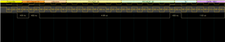
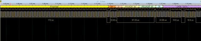
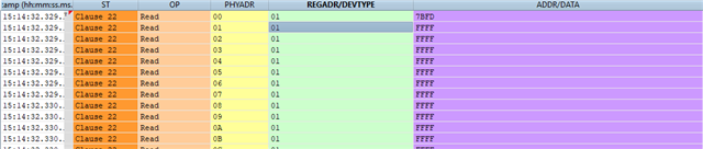
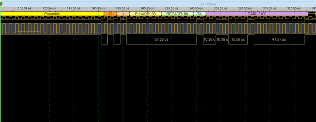
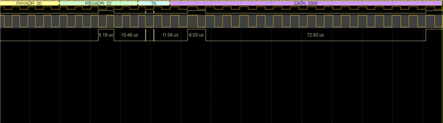
I was implementing the MDIO PHY read and write functionalities considering the work around of errata I2329.
In the TI PDK implementation of this errata, it is found that after writing or reading the PHY register, there is wait time for pull-up to work in the code as shown below
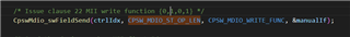
Code from the funcion CpswMdio_manualPhyRegWrite22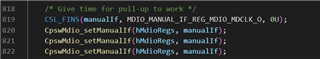
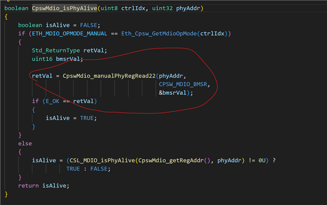
Code from the function 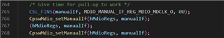
I see the MDIO clock is pulled down for 3 times for writing and 2 times for reading. Please give more insight about this.
What is the minimum time to wait for the write and read operations to be completed?
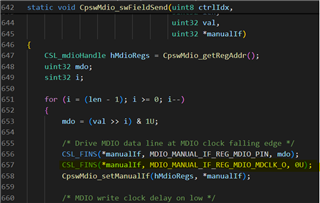
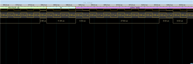
While going through another function CpswMdio_swFieldSend,
static void CpswMdio_swFieldSend(uint8 ctrlIdx,
sint32 len,
uint32 val,
uint32 *manualIf)
{
CSL_mdioHandle hMdioRegs = CpswMdio_getRegAddr();
uint32 mdo;
sint32 i;
for (i = (len - 1); i >= 0; i--)
{
mdo = (val >> i) & 1U;
/* prepare the value of MDIO_MANUAL_IF_REG register */
/* Drive MDIO data line at MDIO clock falling edge */
CSL_FINS(*manualIf, MDIO_MANUAL_IF_REG_MDIO_PIN, mdo);
CSL_FINS(*manualIf, MDIO_MANUAL_IF_REG_MDIO_MDCLK_O, 0U);
CpswMdio_setManualIf(hMdioRegs, *manualIf);
/* MDIO write clock delay on low */
Eth_GetMdioWriteLowDelayNsec(ctrlIdx);
/* MDIO clock rising edge */
CSL_FINS(*manualIf, MDIO_MANUAL_IF_REG_MDIO_MDCLK_O, 1U);
CpswMdio_setManualIf(hMdioRegs, *manualIf);
/* MDIO write clock delay on high */
Eth_GetMdioWriteHighDelayNsec(ctrlIdx);
}
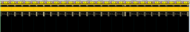
}What is the delay to be introduced between the falling edge and raising edge of the MDIO clock
Kind regards
Thank You
Manisha Narayana Gowda