This thread has been locked.

If you have a related question, please click the "Ask a related question" button in the top right corner. The newly created question will be automatically linked to this question.

AM335X USB eye pattern compliance issue

Other Parts Discussed in Thread: AM3352

Hello,

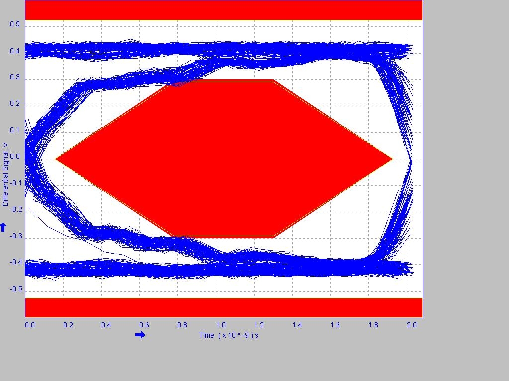
we developed a module using AM3352. The USB outputs are routed as differential pairs with correct differential impedance of 90Ohms and roughly 45 Ohms single ended. When envoking USB test modes and checking on a fast digital scope we find that the eye pattern does not meet USB2.0 high speed requirements. Additional ESD protection was already removed. The silicon used is still first revision, we are currently trying to repeat the measurement on BeagleBone Black which is using newer revision of the chip.

Has Texas Instruments ever verified USB compliance on physical layer by measuring eye pattern ?

Is there anything that can be done to boost the signal i.e. increase slew rate ? We don´t see such options although we have access to the documents that are only available under NDA.

We know there is a bug on first silicon related to USB but this appears to be a different issue

since our module is already in mass production this is a serious problem for us

thanks and regards, Christoph

  • Hello Christoph,

    The answer to your first question is, yes, this device successfully passes the USB-IF electrical tests. The PHY IP used in AM335x has been used on several generations of devices and is quite mature.

    As for your issue, what do your DP/DM trace topologies look like? At first glance this eye appears to show an impedance discontinuity somewhere in your design so I would look for stubs, test points, switches, cables, or other items such as these that could cause this problem.

  • I have inserted the eye diagram measured using AM335x silicon revision 1.0 on the TI general purpose EVM at USBIF workshop #83.

    We have not seen an issue on the TI EVMs. 

    Regards,
    Paul

  • HI Paul, thanks a lot for your fast response. Indeed the situation is a bit more critical on our application since the signal is propagated over two boards and some length of copper tracks. Please let me know if there is any way how the eye pattern can be improved in SW, e.g. by adjusting driver strength. I did not find any such option in technical reference manual and extensions under NDA. I just need to know if there is an option I may have missed.

    Secondly, is there any difference to be expected in the eye pattern between silicon 1.0 and 2.1 ? We don´t have samples of 2.1 on our module yet...

    thanks and regards,

    Christoph

  • Christoph,

    There is no difference in the eye pattern results across silicon revisions.

    Were you able to identify any of the factors I outlined earlier for your poor eye result?

  • Hi Paul,

    The most significant difference between our board and TI EVMs is that the USB connector is not on the same board as AM3352 but there is a SO-DIMM connector in between. This was chosen as a compromise between cost and signal integrity.

    Although we are of course doing all we can to get the routing optimized for high speed it would be very important for us to know if there are any register settings which could have effect on the shape of the USB data lines thus influencing the eye pattern.

    We could not identify any from the documentation we have.

    thanks and regards, Christoph

  • Hello peaves-san,

    Please let me know the condition for the eye diagram.
    1. near end or far end
    2. Tier number (Tier1 - Tier6)

    Best Regards,

    Nomoto

  • This eye diagram was captured with AM335x operating as USB host using the near-end template.  In this case, Tier number doesn't apply.

    Regards,
    Paul 

  • Hello Paul-san,

    Thank you for your reply.
    The information is very helpful.

    Best Regards,

    Nomoto