This thread has been locked.

If you have a related question, please click the "Ask a related question" button in the top right corner. The newly created question will be automatically linked to this question.

No voltage on usb pin1

Other Parts Discussed in Thread: TPS65910

Hi Pavel,

Our custom board have two usb host port .But there both are no voltages on pin1.

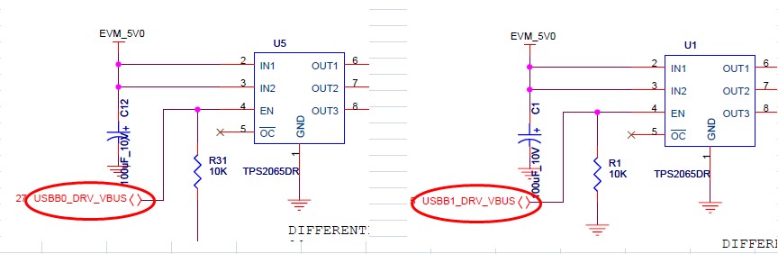
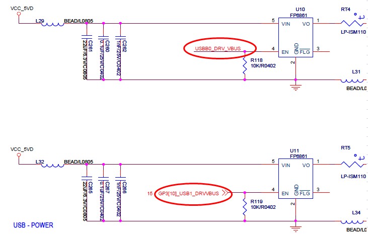
According to the circuit diagram, I know I need enable the power control pin by set GPIO pins to 1.

But I don't know where to set the pins in kernel.

Would you please tell me how to set?

Thank you

Attached figure is the  circuit diagram.

Bob

  • Bob,

    bob lee said:

    But I don't know where to set the pins in kernel.

    Would you please tell me how to set?

    For configure the pins in the linux kernel, refer to the below wiki page:

    http://processors.wiki.ti.com/index.php/TI81XX_PSP_User_Guide#TI814X.2FTI813X

    BR
    Pavel

  • Hi Pavel,

    I have set the pinmux as below.But the board still couldn't detect the U key and pin 1 is still no voltage.

    omap_mux_init_signal("vout1_g_y_yc6.gpio3_10", 1);
     omap_mux_init_signal("usb0_drvvbus.usb0_drvvbus", 1);

    Is it right?

    B/R

    Bob

  • Hi Pavel,

    I find another case.One usb port could detect U key sometimes.

    When I plug the U key before starting kernel,the board could detect the U key sometimes.

    But when I plug the U key after starting kernel,the board couldn't detect the U key .

    BR

    Bob

  • Bob,

    I am not sure I fully understand your query. Can you provide more details. And can you provide console output?

    Best regards,
    Pavel

  • Hi Pavel,

    In general,After configuring the pinmux as below,it still couldn't detect the U key and there are still no voltage.

    omap_mux_init_signal("vout1_g_y_yc6.gpio3_10", 1);
     omap_mux_init_signal("usb0_drvvbus.usb0_drvvbus", 1);

    Is the pinmux configure right?

    Bob

  • Bob,

    bob lee said:
    Is the pinmux configure right?

    You should check this from user space with the devmem2 tool.

    From what I understand, you need to export signal gpio3_10 on the AH27 physical pin (which is controlled from the PINCNTL218/0x48140B64 register/address).

    You can check with the below command (executed on the DM814x board, when everything is boot up and running):

    root@dm814x-evm:~# devmem2 0x48140B64
    /dev/mem opened.
    Memory mapped at address 0x40246000.
    Read at address  0x48140B64 (0x40246b64): 0x00050004

    As you can see by default this pin is set to vin1a_d11 signal. If your pin mux is successful, you should have the value of 0x80 instead of 0x04.

    From what I understand, you need to export signal usb0_drvvbus on physical pin AF11 (which is controlled from the PINCNTL270/0x48140C34 register/address).

    You can check with the below command (executed on the DM814x board, when everything is boot up and running):

    root@dm814x-evm:~# devmem2 0x48140C34
    /dev/mem opened.
    Memory mapped at address 0x4025a000.
    Read at address  0x48140C34 (0x4025ac34): 0x000C0001

    As you can see by default this pin is set to usb0_drvvbus.

    Best regards,
    Pavel

  • Hi Pavel,

    Thank you .

    I am trying according to your guidance.

    BR

    Bob

  • Hi Pavel,

    After setting the pinmux as below,

    omap_mux_init_signal("usb0_drvvbus.usb0_drvvbus", 1); 

    omap_mux_init_signal("vout1_g_y_yc6.gpio3_10", 1);

    In the linux,I can see

    root@dm814x-evm:/# devmem2 0x48140b64
    /dev/mem opened.
    Memory mapped at address 0x4004b000.
    Read at address  0x48140B64 (0x4004bb64): 0x00050004
    root@dm814x-evm:/# devmem2 0x48140c34
    /dev/mem opened.
    Memory mapped at address 0x40092000.
    Read at address  0x48140C34 (0x40092c34): 0x00000001
    root@dm814x-evm:/#

    There are still no voltage .

    We are using usb host mode,Do we need to set the mode to host mode ?

    BR

    Bob

  • Bob,

    bob lee said:
    omap_mux_init_signal("vout1_g_y_yc6.gpio3_10", 1);

    bob lee said:
    root@dm814x-evm:/# devmem2 0x48140b64
    /dev/mem opened.
    Memory mapped at address 0x4004b000.
    Read at address  0x48140B64 (0x4004bb64): 0x00050004

    I am not sure at which part of the linux kernel code you are doing this, but it is most probably overwritten from the below code:

    ti-ezsdk_dm814x-evm_5_05_02_00/board-support/linux-2.6.37-psp04.04.00.01/arch/arm/mach-omap2/devices.c

    static void __init ti81xx_video_mux(void)
    {

    } else if (cpu_is_ti814x())    {

    /*omap_mux_init_signal("vin1a_d11",
                    TI814X_PULL_DIS | TI814X_INPUT_EN);*/
            omap_mux_init_signal("gpio3_10",
                    TI814X_PULL_DIS | TI814X_INPUT_EN);

    Thus I configure the gpio3_10 signal in place of the vin1a_d11 signal:

    root@dm814x-evm:~# devmem2 0x48140B64
    /dev/mem opened.
    Memory mapped at address 0x401ec000.
    Read at address  0x48140B64 (0x401ecb64): 0x00050080

    bob lee said:
    We are using usb host mode,Do we need to set the mode to host mode ?

    I think yes. Refer to the below wiki pages:

    http://processors.wiki.ti.com/index.php/TI81XX_PSP_USB_Driver_User_Guide

    http://processors.wiki.ti.com/index.php/DM81xx_AM38XX_USB_User_Guide#USB_ID_configuration_for_DM814x

    http://processors.wiki.ti.com/index.php/DM81xx_AM38XX_USB_User_Guide#The_driver_supports_the_following_features_for_USB_Host_.28DM816X.2FDM814X.29

    http://processors.wiki.ti.com/index.php/Usbgeneralpage#USB_controller_in_host_mode

    http://processors.wiki.ti.com/index.php/Usbgeneralpage#Host_mode_applications

    Regards,
    Pavel

  • Hi Pavel,

    The pinmux setting is ok now.

    During the booting,I find one message “ti81xx_interrupt 909: VBUS error workaround (delay coming)”.

    Does it matter?

    BR

    Bob

  • Bob,

    Can you provide the whole boot console log for analysis.

    BR
    Pavel

  • Pavel,

    Here is the log below.

    Starting kernel ...

    Uncompressing Linux... done, booting the kernel.
    Linux version 2.6.37+ (boblee@javenshen-desktop) (gcc version 4.3.3 (Sourcery G++ Lite 2009q1-203) ) #643 Mon Jul 28 18:34:23 CST 2014
    CPU: ARMv7 Processor [413fc082] revision 2 (ARMv7), cr=10c53c7f
    CPU: VIPT nonaliasing data cache, VIPT aliasing instruction cache
    Machine: ti8148evm
    bootconsole [earlycon0] enabled
    reserved size = 52428800 at 0x0
    FB: Reserving 52428800 bytes SDRAM for VRAM
    Memory policy: ECC disabled, Data cache writeback
    OMAP chip is TI8148 3.0
    SRAM: Mapped pa 0x402f1000 to va 0xfe400000 size: 0xf000
    Built 1 zonelists in Zone order, mobility grouping on.  Total pages: 247296
    Kernel command line: mem=1024M console=ttyO0,115200n8 earlyprintk root=/dev/ram rw initrd=0x82000000,32MB
    PID hash table entries: 4096 (order: 2, 16384 bytes)
    Dentry cache hash table entries: 131072 (order: 7, 524288 bytes)
    Inode-cache hash table entries: 65536 (order: 6, 262144 bytes)
    Memory: 974MB = 974MB total
    Memory: 949856k/949856k available, 98720k reserved, 210944K highmem
    Virtual kernel memory layout:
        vector  : 0xffff0000 - 0xffff1000   (   4 kB)
        fixmap  : 0xfff00000 - 0xfffe0000   ( 896 kB)
        DMA     : 0xffc00000 - 0xffe00000   (   2 MB)
        vmalloc : 0xf0800000 - 0xf8000000   ( 120 MB)
        lowmem  : 0xc0000000 - 0xf0000000   ( 768 MB)
        pkmap   : 0xbfe00000 - 0xc0000000   (   2 MB)
        modules : 0xbf000000 - 0xbfe00000   (  14 MB)
          .init : 0xc0008000 - 0xc003b000   ( 204 kB)
          .text : 0xc003b000 - 0xc0510000   (4948 kB)
          .data : 0xc0510000 - 0xc0557880   ( 287 kB)
    SLUB: Genslabs=11, HWalign=64, Order=0-3, MinObjects=0, CPUs=1, Nodes=1
    NR_IRQS:375
    IRQ: Found an INTC at 0xfa200000 (revision 5.0) with 128 interrupts
    Total of 128 interrupts on 1 active controller
    GPMC revision 6.0
    Trying to install interrupt handler for IRQ368
    Trying to install interrupt handler for IRQ369
    Trying to install interrupt handler for IRQ370
    Trying to install interrupt handler for IRQ371
    Trying to install interrupt handler for IRQ372
    Trying to install interrupt handler for IRQ373
    Trying to install interrupt handler for IRQ374
    Trying to install type control for IRQ375
    Trying to set irq flags for IRQ375
    OMAP clockevent source: GPTIMER1 at 20000000 Hz
    Console: colour dummy device 80x30
    Calibrating delay loop... 599.65 BogoMIPS (lpj=2998272)
    pid_max: default: 32768 minimum: 301
    Security Framework initialized
    Mount-cache hash table entries: 512
    CPU: Testing write buffer coherency: ok
    devtmpfs: initialized
    omap_voltage_early_init: voltage driver support not added
    regulator: core version 0.5
    regulator: dummy:
    NET: Registered protocol family 16
    omap_voltage_domain_lookup: Voltage driver init not yet happened.Faulting!
    omap_voltage_add_dev: VDD specified does not exist!
    OMAP GPIO hardware version 0.1
    OMAP GPIO hardware version 0.1
    OMAP GPIO hardware version 0.1
    OMAP GPIO hardware version 0.1
    omap_mux_init: Add partition: #1: core, flags: 4
    NOR: Can't request GPMC CS
    Debugfs: Only enabling/disabling deep sleep and wakeup timer is supported now
    registered ti81xx_vpss device
    registered ti81xx_vidout device
    registered ti81xx on-chip HDMI device
    registered ti81xx_fb device
    registered ti81xx_vin device
    bio: create slab <bio-0> at 0
    SCSI subsystem initialized
    usbcore: registered new interface driver usbfs
    usbcore: registered new interface driver hub
    usbcore: registered new device driver usb
    USBSS revision 4ea2080b
    registerd cppi-dma Intr @ IRQ 17
    Cppi41 Init Done
    omap_i2c omap_i2c.1: bus 1 rev4.0 at 100 kHz
    pcf857x: probe of 1-0021 failed with error -121
    tps65910 1-002d: read from reg 3f failed
    tps65910 1-002d: read from reg 1e failed
    set_machine_constraints: failed to enable VRTC
    tps65910 1-002d: failed to register tps65910-pmic regulator
    tps65910-pmic: probe of tps65910-pmic failed with error -121
    tps65910 1-002d: No interrupt support, no core IRQ
    omap_i2c omap_i2c.3: bus 3 rev4.0 at 100 kHz
    Advanced Linux Sound Architecture Driver Version 1.0.23.
    Switching to clocksource gp timer
    musb-hdrc: version 6.0, host, debug=0
    musb-hdrc musb-hdrc.0: dma type: dma-cppi41
    MUSB controller-0 revision 4ea20800
    musb-hdrc musb-hdrc.0: MUSB HDRC host driver
    musb-hdrc musb-hdrc.0: new USB bus registered, assigned bus number 1
    usb usb1: New USB device found, idVendor=1d6b, idProduct=0002
    usb usb1: New USB device strings: Mfr=3, Product=2, SerialNumber=1
    usb usb1: Product: MUSB HDRC host driver
    usb usb1: Manufacturer: Linux 2.6.37+ musb-hcd
    usb usb1: SerialNumber: musb-hdrc.0
    hub 1-0:1.0: USB hub found
    hub 1-0:1.0: 1 port detected
    musb-hdrc musb-hdrc.0: USB Host mode controller at f081e000 using DMA, IRQ 18
    musb-hdrc musb-hdrc.1: dma type: dma-cppi41
    MUSB controller-1 revision 4ea20800
    musb-hdrc musb-hdrc.1: MUSB HDRC host driver
    musb-hdrc musb-hdrc.1: new USB bus registered, assigned bus number 2
    usb usb2: New USB device found, idVendor=1d6b, idProduct=0002
    usb usb2: New USB device strings: Mfr=3, Product=2, SerialNumber=1
    usb usb2: Product: MUSB HDRC host driver
    usb usb2: Manufacturer: Linux 2.6.37+ musb-hcd
    usb usb2: SerialNumber: musb-hdrc.1
    hub 2-0:1.0: USB hub found
    ti81xx_interrupt 909: VBUS error workaround (delay coming)
    hub 2-0:1.0: 1 port detected
    musb-hdrc musb-hdrc.1: USB Host mode controller at f0828800 using DMA, IRQ 19
    NET: Registered protocol family 2
    IP route cache hash table entries: 32768 (order: 5, 131072 bytes)
    TCP established hash table entries: 131072 (order: 8, 1048576 bytes)
    TCP bind hash table entries: 65536 (order: 6, 262144 bytes)
    TCP: Hash tables configured (established 131072 bind 65536)
    TCP reno registered
    UDP hash table entries: 512 (order: 1, 8192 bytes)
    UDP-Lite hash table entries: 512 (order: 1, 8192 bytes)
    NET: Registered protocol family 1
    RPC: Registered udp transport module.
    RPC: Registered tcp transport module.
    RPC: Registered tcp NFSv4.1 backchannel transport module.
    Trying to unpack rootfs image as initramfs...
    rootfs image is not initramfs (no cpio magic); looks like an initrd
    Freeing initrd memory: 32768K
    NetWinder Floating Point Emulator V0.97 (double precision)
    PMU: registered new PMU device of type 0
    omap-iommu omap-iommu.0: ducati registered
    omap-iommu omap-iommu.1: sys registered
    highmem bounce pool size: 64 pages
    JFFS2 version 2.2. (NAND) 漏 2001-2006 Red Hat, Inc.
    msgmni has been set to 1507
    io scheduler noop registered
    io scheduler deadline registered
    io scheduler cfq registered (default)
    Serial: 8250/16550 driver, 4 ports, IRQ sharing enabled
    omap_uart.0: ttyO0 at MMIO 0x48020000 (irq = 72) is a OMAP UART0
    console [ttyO0] enabled, bootconsole disabled
    console [ttyO0] enabled, bootconsole disabled
    omap_uart.1: ttyO1 at MMIO 0x48022000 (irq = 73) is a OMAP UART1
    omap_uart.2: ttyO2 at MMIO 0x48024000 (irq = 74) is a OMAP UART2
    omap_uart.3: ttyO3 at MMIO 0x481a6000 (irq = 44) is a OMAP UART3
    omap_uart.4: ttyO4 at MMIO 0x481a8000 (irq = 45) is a OMAP UART4
    omap_uart.5: ttyO5 at MMIO 0x481aa000 (irq = 46) is a OMAP UART5
    brd: module loaded
    loop: module loaded
    omap2-nand driver initializing
    NAND device: Manufacturer ID: 0xec, Chip ID: 0xda (Samsung )
    Creating 6 MTD partitions on "omap2-nand.0":
    0x000000000000-0x000000020000 : "U-Boot-min"
    0x000000020000-0x000000260000 : "U-Boot"
    0x000000260000-0x000000280000 : "U-Boot Env"
    0x000000280000-0x0000006c0000 : "Kernel"
    0x0000006c0000-0x00000cee0000 : "File System"
    0x00000cee0000-0x000010000000 : "Reserved"
    davinci_mdio davinci_mdio.0: davinci mdio revision 1.6
    davinci_mdio davinci_mdio.0: detected phy mask fffffff9
    davinci_mdio.0: probed
    davinci_mdio davinci_mdio.0: phy[1]: device 0:01, driver RTL821x Gigabit Ethernet
    davinci_mdio davinci_mdio.0: phy[2]: device 0:02, driver RTL821x Gigabit Ethernet
    CAN device driver interface
    CAN bus driver for Bosch D_CAN controller 1.0
    d_can d_can: d_can device registered (irq=52, irq_obj=53)
    usbcore: registered new interface driver cdc_ether
    usbcore: registered new interface driver dm9601
    usbcore: registered new interface driver cdc_acm
    cdc_acm: v0.26:USB Abstract Control Model driver for USB modems and ISDN adapters
    Initializing USB Mass Storage driver...
    usbcore: registered new interface driver usb-storage
    USB Mass Storage support registered.
    mice: PS/2 mouse device common for all mice
    qt602240_ts 1-004a: __qt602240_read_reg: i2c transfer failed
    qt602240_ts: probe of 1-004a failed with error -5
    omap_rtc omap_rtc: rtc core: registered omap_rtc as rtc0
    i2c /dev entries driver
    Linux video capture interface: v2.00
    usbcore: registered new interface driver uvcvideo
    USB Video Class driver (v1.0.0)
    OMAP Watchdog Timer Rev 0x00: initial timeout 60 sec
    usbcore: registered new interface driver usbhid
    usbhid: USB HID core driver
    usbcore: registered new interface driver snd-usb-audio
    asoc: tlv320aic3x-hifi <-> davinci-mcasp.2 mapping ok
    ALSA device list:
      #0: TI81XX EVM
    IPVS: Registered protocols ()
    IPVS: Connection hash table configured (size=4096, memory=32Kbytes)
    IPVS: ipvs loaded.
    TCP cubic registered
    NET: Registered protocol family 17
    can: controller area network core (rev 20090105 abi 8)
    NET: Registered protocol family 29
    can: raw protocol (rev 20090105)
    can: broadcast manager protocol (rev 20090105 t)
    Registering the dns_resolver key type
    VFP support v0.3: implementor 41 architecture 3 part 30 variant c rev 3
    omap_voltage_late_init: Voltage driver support not added
    Power Management for TI81XX.
    Detected MACID=84:7e:40:ea:5f:6c
    omap_rtc omap_rtc: setting system clock to 2000-01-01 00:00:00 UTC (946684800)
    RAMDISK: gzip image found at block 0
    VFS: Mounted root (ext2 filesystem) on device 1:0.
    devtmpfs: mounted
    Freeing init memory: 204K
    INIT: version 2.86 booting
    Please wait: booting...
    Error opening /dev/fb0: No such file or directory
    Starting udev
    WARNING: -e needs -E or -F
    udevd (78): /proc/78/oom_adj is deprecated, please use /proc/78/oom_score_adj instead.
    Remounting root file system...
    Caching udev devnodes
    ALSA: Restoring mixer settings...
    No state is present for card EVM
    Found hardware: "" "" "" "" ""
    Hardware is initialized using a generic method
    No state is present for card EVM
    Configuring e2fsprogs.
    update-alternatives: Error: cannot register alternative chattr to /usr/bin/chattr since it is already registered to /bin/chattr
    update-alternatives: Linking //sbin/uuidd to uuidd.util-linux-ng
    Configuring update-modules.
    Configuring dbus.
     Adding system startup for /etc/init.d/dbus-1.
    Configuring network interfaces...
    CPSW phy found : id is : 0x1cc912

    CPSW phy found : id is : 0x1cc912
    udhcpc (v1.13.2) started
    Sending discover...
    PHY: 0:02 - Link is Up - 0/Half
    PHY: 0:02 - Link is Down
    PHY: 0:01 - Link is Up - 100/Full
    Sending discover...
    Sending select for 192.168.5.101...
    Lease of 192.168.5.101 obtained, lease time 7200
    adding dns 192.168.5.1
    adding dns 192.168.6.9
    done.
    Setting up IP spoofing protection: rp_filter.
    Mon Dec 31 10:37:00 UTC 2012
    INIT: Entering runlevel: 5
    Starting system message bus: dbus.
    Starting telnet daemon.
    Starting syslogd/klogd: done
    Starting thttpd.

     _____                    _____           _         _  
    |  _  |___ ___ ___ ___   |  _  |___ ___  |_|___ ___| |_
    |     |  _| .'| . | . |  |   __|  _| . | | | -_|  _|  _|
    |__|__|_| |__,|_  |___|  |__|  |_| |___|_| |___|___|_| 
                  |___|                    |___|           

    Arago Project http://arago-project.org dm814x-evm ttyO0

    Arago 2011.09 dm814x-evm ttyO0

    dm814x-evm login: root

    BR

    Bob

  • Hi Pavel,

    The error is related to the USB controller,is it right?

    Bob

  • Hi Bob,

    I do not observe this line at my side, so this should be an error, this is what I have:

    musb-hdrc: version 6.0, host, debug=0
    musb-hdrc musb-hdrc.0: dma type: dma-cppi41
    MUSB controller-0 revision 4ea20800
    musb-hdrc musb-hdrc.0: MUSB HDRC host driver
    musb-hdrc musb-hdrc.0: new USB bus registered, assigned bus number 1
    usb usb1: New USB device found, idVendor=1d6b, idProduct=0002
    usb usb1: New USB device strings: Mfr=3, Product=2, SerialNumber=1
    usb usb1: Product: MUSB HDRC host driver
    usb usb1: Manufacturer: Linux 2.6.37 musb-hcd
    usb usb1: SerialNumber: musb-hdrc.0
    hub 1-0:1.0: USB hub found
    hub 1-0:1.0: 1 port detected
    musb-hdrc musb-hdrc.0: USB Host mode controller at d081e000 using DMA, IRQ 18
    musb-hdrc musb-hdrc.1: dma type: dma-cppi41
    MUSB controller-1 revision 4ea20800
    musb-hdrc musb-hdrc.1: MUSB HDRC host driver
    musb-hdrc musb-hdrc.1: new USB bus registered, assigned bus number 2
    usb usb2: New USB device found, idVendor=1d6b, idProduct=0002
    usb usb2: New USB device strings: Mfr=3, Product=2, SerialNumber=1
    usb usb2: Product: MUSB HDRC host driver
    usb usb2: Manufacturer: Linux 2.6.37 musb-hcd
    usb usb2: SerialNumber: musb-hdrc.1
    hub 2-0:1.0: USB hub found
    hub 2-0:1.0: 1 port detected
    musb-hdrc musb-hdrc.1: USB Host mode controller at d0826800 using DMA, IRQ 19

    When I boot up, I can use usb0 and usb1 as host ports, thus attach a mouse to them:

    root@dm814x-evm:~# usb 1-1: new low speed USB device using musb-hdrc and address 2
    usb 1-1: New USB device found, idVendor=093a, idProduct=2516
    usb 1-1: New USB device strings: Mfr=0, Product=2, SerialNumber=0
    usb 1-1: Product: USB OPTICAL MOUSE
    input: USB OPTICAL MOUSE as /devices/platform/omap/ti81xx-usbss/musb-hdrc.0/usb1/1-1/1-1:1.0/input/input1
    generic-usb 0003:093A:2516.0001: input: USB HID v1.11 Mouse [USB OPTICAL MOUSE] on usb-musb-hdrc.0-1/input0

    root@dm814x-evm:~# usb 1-1: USB disconnect, address 2

    root@dm814x-evm:~# usb 2-1: new low speed USB device using musb-hdrc and address 2
    usb 2-1: New USB device found, idVendor=093a, idProduct=2516
    usb 2-1: New USB device strings: Mfr=0, Product=2, SerialNumber=0
    usb 2-1: Product: USB OPTICAL MOUSE
    input: USB OPTICAL MOUSE as /devices/platform/omap/ti81xx-usbss/musb-hdrc.1/usb2/2-1/2-1:1.0/input/input2
    generic-usb 0003:093A:2516.0002: input: USB HID v1.11 Mouse [USB OPTICAL MOUSE] on usb-musb-hdrc.1-1/input0

    root@dm814x-evm:~# usb 2-1: USB disconnect, address 2

    From the log you have sent me, it looks like only usb2-1 is impacted, as this error does not occur for usb1-1.

    Can you try attach mouse (or other gadget) on usb0 (usb1-1)?

    Also, are you sure you have ground the USB_ID pin to 0V?

    Regards,
    Pavel

  • Bob,

    bob lee said:
    During the booting,I find one message “ti81xx_interrupt 909: VBUS error workaround (delay coming)”.

    See the below e2e threads which discuss the similar issue:

    http://e2e.ti.com/support/arm/sitara_arm/f/791/t/299558.aspx

    http://e2e.ti.com/support/arm/sitara_arm/f/791/t/284834.aspx

    http://e2e.ti.com/support/arm/sitara_arm/f/791/t/299887.aspx

     http://e2e.ti.com/support/arm/sitara_arm/f/791/t/233404.aspx

    http://e2e.ti.com/support/arm/sitara_arm/f/791/t/316037.aspx

    Regards,
    Pavel

  • Hi Pavel,

    Can you try attach mouse (or other gadget) on usb0 (usb1-1)?

    The two usb ports both couldn't detect the mouse.

    Also, are you sure you have ground the USB_ID pin to 0V?

    We have grounded the USB_ID pin to 0V.

    We use usb host mode and I find something different between our custom board and evm board.

    Please refer to the attached circuit diagram.

    evm board:

    our custom board:

  • Pavel,

    But I don't know how to configure the pins.That is to say,I don't know where to configure in the kernel code.

    BR

    Bob

  • And I find the the message "ti81xx_interrupt 909: VBUS error workaround (delay coming)"  in the  drivers/usb/musb/ti81xx.c(static irqreturn_t ti81xx_interrupt(int irq, void *hci);).

    Bob

  • Bob,

    The USB PHY does not have a built-in charge pump and an external power source is required to source the 5V VBUS power. The PHY has built in charge detection for device mode and control capability for host application for implementing external charge detection capability.

    The USB0/1_DRV_VBUS pins are output from the DM814x device, these signals are used by the USB0/1 Controller to enable the external VBUS charge pump.

    USB0/1_VBUS pins are input to the DM814x (VBUS comparator input). These analog input pins sense the level of the USB VBUS voltage and should connect directly to the USB VBUS voltage.

    Is your DM814x custom board schematic aligned with the above?

    We have also some wiki page that might be in help:

    http://processors.wiki.ti.com/index.php/AM335x_Schematic_Checklist#USB

    Typical connections for a USB host:

    • USBx_DP and USBx_DM are connected directly to the USB connector
    • USBx_CE is typically not used and can be left unconnected
    • USDx_ID should be grounded
    • USBx_DRVVBUS should be connected to the enable of the 5V VBUS power source.
    • USBx_VBUS should be connected to the output of the 5V VBUS power source


    Regards,
    Pavel

  • Pavel,

    Is your DM814x custom board schematic aligned with the above?

    Yes,you're right.

    BR

    Bob


  • Hi Pavel,

    I have checked our board.The below replies maybe help.

    Typical connections for a USB host:

    • USBx_DP and USBx_DM are connected directly to the USB connector

    It is ok.

    • USBx_CE is typically not used and can be left unconnected

    I don't find USBx_CE.

    • USDx_ID should be grounded

    It is ok.

    • USBx_DRVVBUS should be connected to the enable of the 5V VBUS power source

    It is ok.

             USBx_VBUS should be connected to the output of the 5V VBUS power source

    It is ok.

    BR

    Bob

  • Bob,

    Let us first check USB0.

    USB0 has only one pin that can be controlled through the registers: USB0_DRVVBUS controlled through PINCNTL270/0x48140C34.

    On EVM, the PINCNTL270 value is 0x000C0001. Can you check (with devmem2) you have the same at your side?

    Also, can you try to attach the external device you have on TI 8148 EVM (not only to custom board) and verify that this device can be detected and recognized by the TI EVM?

    This wiki page might be also in help:

    http://processors.wiki.ti.com/index.php/TI81xx_PSP_Porting_Guide#USB_driver

    Best regards,
    Pavel

  • Hi Pavel,

    On EVM, the PINCNTL270 value is 0x000C0001. Can you check (with devmem2) you have the same at your side?

    At my side, the PINCNTL270 value is  0x00040001.

    Also, can you try to attach the external device you have on TI 8148 EVM (not only to custom board) and verify that this device can be detected and recognized by the TI EVM?

    I'm sorry for there are only custom board at my side and no TI8148 EVM board.

    BR

    Bob


  • Bob,

    bob lee said:
    At my side, the PINCNTL270 value is  0x00040001.

    This means you have PINCNTL270 [19] bit = 0, which violates the DM814x datasheet and DM814x SiliconErrata:

    DM814x datasheet:

    Table 4-11. PINCNTL1 – PINCNTL270 (PINCNTLx) Registers Bit Descriptions
    19 RSV Reserved. This bit must always be written with the reset (default) value.

    PINCNTL270 reset value is 0x000C0000.

    DM814x Silicon Errata:

    Advisory 2.1.88 Control Module, Pin Configuration (PINCNTLx): ROM Modifies Bit 19


    Can you check where exactly in the code you change that bit from 1 to 0?

    BR
    Pavel

  • Hi Pavel,

    To be frank, I don't do any change to set the bit 19 from 1 to 0 and only add the code "omap_mux_init_signal("gpio3_10", TI814X_PULL_UP);" to function ti81xx_video_mux(void) to set pinmux.

    BR

    Bob

  • Bob,

    bob lee said:
    To be frank, I don't do any change to set the bit 19 from 1 to 0 and only add the code "omap_mux_init_signal("gpio3_10", TI814X_PULL_UP);" to function ti81xx_video_mux(void) to set pinmux.

    I tried this, but this change does not impact the PINCNTL270 register value, it is still 0x000C0001.

    I changed it with pure register write, but I am still able to detect the mouse on usb0 host port, so this should not be the root cause.

    root@dm814x-evm:~# devmem2 0x48140C34
    /dev/mem opened.
    Memory mapped at address 0x40108000.
    Read at address  0x48140C34 (0x40108c34): 0x00040001
    root@dm814x-evm:~# usb 1-1: new low speed USB device using musb-hdrc and address 2
    usb 1-1: New USB device found, idVendor=093a, idProduct=2516
    usb 1-1: New USB device strings: Mfr=0, Product=2, SerialNumber=0
    usb 1-1: Product: USB OPTICAL MOUSE
    input: USB OPTICAL MOUSE as /devices/platform/omap/ti81xx-usbss/musb-hdrc.0/usb1/1-1/1-1:1.0/input/input1
    generic-usb 0003:093A:2516.0001: input: USB HID v1.11 Mouse [USB OPTICAL MOUSE] on usb-musb-hdrc.0-1/input0

    Can you double check your HW design, I suspect this might be HW related issue?

    BR
    Pavel

  • Hi Pavel,

    I have checked the HW design with our HW engineer and there is nothing wrong.

    BR

    Bob

  • Hi Pavel,

    The file below is the circuit diagram for usb.Please refer to it.Thank you.

    7077.usb.pdf

    BR

    Bob

  • Hi Pavel,

    For another usb, I set pinmux(omap_mux_init_signal("gpio3_10", TI814X_PULL_UP);).But the voltage of gpio3_10  is ony 0.91v,not 5v.

    BR

    Bob

  • Hi Pavel,

    The reason why the output voltage of gpio3_10 is only 0.91v not 3.3v is that I have not set the gpio to output mode.

    Would you please tell me how to set the gpio to output mode ?

    BR

    Bob

  • Bob,

    bob lee said:
    Would you please tell me how to set the gpio to output mode ?

    Refer to the below wiki page:

    http://processors.wiki.ti.com/index.php/TI81XX_PSP_GPIO_Driver_User_Guide#Kernel_Level

    BR
    Pavel

  • Hi Pavel,

    Can I use the function "static int gpio_output(struct gpio_chip *chip, unsigned offset, int value)" in Gpio.c?

    BR

    Bob

  • Bob,

    bob lee said:
    The reason why the output voltage of gpio3_10 is only 0.91v not 3.3v

    The VBUS input signals should be 5V. See some extracts from the DM814x USB TRM:

    25.3.5 USB Pins
    The USB subsystem external interface signals comprises two differential data lines, two Voltage Buses Level Detection Pins (VBUSIN), and two USB DRVVBUS signals which are used to enable/disable external 5V Power Source.

    25.5.4 VBUS Voltage Sourcing Control
    When any of the USB controllers assumes the role of a host, the USB is required to supply a +5V power source to an attached device(s) through the VBUS line. In order to achieve this task, the USB controller requires the use of an external power logic (or charge pump) capable of sourcing 5V power. The USB_DRVVBUS pin is used as a control signal to enable/disable this external power supply. The control on the USB_DRVVBUS is automatic and is handled by the USB controller. The control should be transparent to the user so long as the proper hardware connection and software initialization are in place. The USB controller drives the USB_DRVVBUS signal high when it assumes the role of a host during a valid USB session. When assuming the role of a device, the controller drives the USB_DRVVBUS signal low disabling the external charge pump; hence, no power is driven on the VBUS line by the controller. 5V VBUS is expected to be sourced by the external USB Host.
    Note that when both USB Modules are self-powered and the device does not rely on the voltage on the VBUS voltage sourced by an external USB Host for controller operation when operating as a USB Device. The Voltage Level detected on the +5V VBUS is used to identify the presence of a Host and to power up the internal pull-up on the D+ line. The USB PHY continually monitors the voltage on the USB_VBUSIN and reports the status to USB controller.

    25.5.1.1 USB Controller Role Assuming Method

    If the USB controller determines it is the A-Device it will turn on VBUS and wait until the USBx_VBUSIN pin is >= 4.4V. Assuming that the voltage level of the USBX_VBUSIN is found to within the VBUS Valid range according to the USB 2.0 Specification, the controller will then default to the USB Host and wait for a device to connect to the bus before attempting to enumerate the device.


    If you see the VBUS is not above valid, you must review VBUS circuit and see why VBUS is getting drop.


    See also the below wiki pages, which discuss drvvbus controlled with GPIO:

    http://e2e.ti.com/support/arm/sitara_arm/f/791/t/270060.aspx

    http://e2e.ti.com/support/dsp/davinci_digital_media_processors/f/716/t/229405.aspx

    http://e2e.ti.com/support/dsp/davinci_digital_media_processors/f/716/t/223771.aspx

    http://e2e.ti.com/support/dsp/davinci_digital_media_processors/f/100/t/40050.aspx

    BR
    Pavel

  • Hi Pavel,

    The VBUS input signals both are  5V.

    But the two USB DRVVBUS signals are 0.91v.There are all too low to enable external 5V Power Source.

    I don't know how to set the gpio pins to output mode and failed to set the gpio pins to output mode.

    Would you please give me more detailed guidance?

    BR

    Bob

  • Bob,

    bob lee said:

    But the two USB DRVVBUS signals are 0.91v.There are all too low to enable external 5V Power Source.

    I don't know how to set the gpio pins to output mode and failed to set the gpio pins to output mode.

    But USB0_DRVVBUS (AF11) pin is not used as GPIO pin, but as a USB0_DRVVBUS pin. Then how setting gpio pins to output mode will impact the USB0_DRVVBUS voltage level?

    BR
    Pavel

  • Hi Pavel,

    Sorry,I don't make my question clear.

    There are two usb port on our board.

    One is controlled by USB0_DRVVBUS,but another one is controlled by gpio3_10 not USB1_DRVVBUS.

    I want to know how to set gpio3_10 to output mode to enable the  external 5V Power Source.

    Thanks

    BR

    Bob

  • I find GPIO_SETDATAOUT Register to set gpio to output mode in TRM.But I don't find how to set in the kernel code.

    BR

    Bob

  • Bob,

    To make a GPIO pin as output and set the value as high, you can use the gpio_direction_output() function:

    http://processors.wiki.ti.com/index.php/TI81XX_PSP_GPIO_Driver_User_Guide#Kernel_Level

    Make pin 30 as output and set the value as high.

    gpio_direction_output(30, 1);

    Some examples you can find in:

    ti-ezsdk_dm814x-evm_5_05_02_00/board-support/linux-2.6.37-psp04.04.00.01/arch/arm/mach-omap2/devices.c

    /* gpio1_22 controls the GPMC higher address lines a12 -25 */
    #define GPIO_NOR    54

    static void ti814x_nor_init(void)
    {

    int error = 0;

    error = gpio_request(GPIO_NOR, "gpio_nor");
        if (error) {
            printk(KERN_ERR "%s: failed to request GPIO for NOR"
                ": %d\n", __func__, error);
            return;
        }
        gpio_direction_output(GPIO_NOR, 0x0);
        gpio_export(GPIO_NOR, true);

    }

    ti-ezsdk_dm814x-evm_5_05_02_00/board-support/linux-2.6.37-psp04.04.00.01/arch/arm/mach-omap2
    /board-ti8148evm.c

    #define GPIO_LCD_PWR_DOWN    0

    static int setup_gpio_ioexp(struct i2c_client *client, int gpio_base,
         unsigned ngpio, void *context) {
        int ret = 0;
        int gpio = gpio_base + GPIO_LCD_PWR_DOWN;

        ret = gpio_request(gpio, "lcd_power");
        if (ret) {
            printk(KERN_ERR "%s: failed to request GPIO for LCD Power"
                ": %d\n", __func__, ret);
            return ret;
        }

        gpio_export(gpio, true);
        gpio_direction_output(gpio, 0);

        return 0;
    }

    ti-ezsdk_dm814x-evm_5_05_02_00/board-support/linux-2.6.37-psp04.04.00.01/arch/arm/mach-omap2
    /board-ti8168evm.c

    static int __init ti8168_evm_gpio_setup(void)
    {
        /* GPIO-20 should be low for NOR access beyond 4KiB */
        gpio_request(20, "nor");
        gpio_direction_output(20, 0x0);
        return 0;
    }


    ti-ezsdk_dm814x-evm_5_05_02_00/board-support/linux-2.6.37-psp04.04.00.01/Documentation/gpio.txt

    BR
    Pavel


  • Bob,

    You can also have a look in the below e2e threads for how to control the GPIO:

    http://e2e.ti.com/support/dsp/davinci_digital_media_processors/f/716/p/236579/832712.aspx#832712

    http://e2e.ti.com/support/dsp/davinci_digital_media_processors/f/716/t/179780.aspx

    http://e2e.ti.com/support/dsp/davinci_digital_media_processors/f/716/t/298256.aspx

    http://e2e.ti.com/support/dsp/davinci_digital_media_processors/f/717/t/275822.aspx

    http://e2e.ti.com/support/arm/sitara_arm/f/791/t/152100.aspx

    BR
    Pavel

  • Hi Pavel,

    For example,I want to set gpio3_10 and gpio0_7 as output pin and set their value as high,how to do ?

    I don't  understand " pin 30 ".

    BR

    Bob

  • Bob,

    This is explained in the wiki page I have already provided to you:

    http://processors.wiki.ti.com/index.php/TI81XX_PSP_GPIO_Driver_User_Guide

    Linux GPIO numbers start from "0".

    For example the TI814x has 4 banks of 32 GPIOs, for a total of 128 GPIO, i.e Bank-0[0..31], Bank-1[0..31], Bank-2[0..31], Bank-3[0..31].

    In this case Bank-1[0..31] maps to Linux GPIO numbers 32..63, Bank-2[0..31] to Linux GPIO numbers 64..95 etc.

    gpio0_30 is pin 30

    gpio0_7 is pin 7

    gpio3_10 is pin 106

    BR
    Pavel

  • Hi Pavel,

    I'm glad to tell you it is ok now.Thanks for your detailed guidance.

    There is still another problem about the message "ti81xx_interrupt 909: VBUS error workaround (delay coming)".

    I find if the value of musb->int_usb is 0,then the board could detect the u stick.

    But  if the value of musb->int_usb is 128,then the board could not detect the u stick.

    PS:the evm board use USBB0_DRV_VBUS and USBB1_DRV_VBUS to enable the  external 5V Power Source.

    our custom use USBB0_DRV_VBUS and GP3[10] to enable the  external 5V Power Source.

    BR

    Bob

  • Hi Pavel,

    Do I need to  switch off USB1_DRVVBUS pin ?

    BR

    Bob

  • Bob,

    bob lee said:
    our custom use USBB0_DRV_VBUS and GP3[10] to enable the  external 5V Power Source.

    Why you do not use the USB1_DRVVBUS instead of GP3[10]?

    The USB1_DRVVBUS is configured in PINCNTL14/0x48140834. I see that the value for USB1_DRVVBUS is set in the u-boot:

    TI8148_EVM#md 0x48140834
    48140834: 000c0080

    Then we have the same value in linux:

    root@dm814x-evm:~# devmem2 0x48140834
    /dev/mem opened.
    Memory mapped at address 0x400be000.
    Read at address  0x48140834 (0x400be834): 0x000C0080

    When I change this value in u-boot, and set it to MCA[0]_AXR[7] pin (not to USB1_DRVVBUS) I have "hub 2-0:1.0: over-current change on port 1" messages during linux kernel boot:

    TI8148_EVM#mw 0x48140834 0x000C0002
    TI8148_EVM#md 0x48140834
    48140834: 000c0002

    Starting kernel ...

    Uncompressing Linux... done, booting the kernel.

    hub 2-0:1.0: over-current change on port 1
    hub 2-0:1.0: over-current change on port 1
    hub 2-0:1.0: over-current change on port 1

    This make me think that the USB1_DRVVBUS pin is used in the linux kernel (may be from the USB driver), thus linux kernel modification is needed.

    Regards,
    Pavel

  • Hi Pavel,

    The USB1_DRVVBUS is used for audio.So we have to use gpio3_10.

    Could you tell me how to solve the problem?

    Could we switch off the USB1_DRVVBUS?

    BR

    Bob

  • Bob,

    bob lee said:

    Could you tell me how to solve the problem?

    Could we switch off the USB1_DRVVBUS?

    You should switch off the USB1_DRVVBUS and replace its functionality in the linux kernel with the gpio3_10.

    BR
    Pavel

  • Hi Pavel,

    I don't know how to swtich off the USB1_DRVVBUS.

    Would you please tell me how to do ?

    Thanks

    BR

    Bob

  • Bob,

    I made a consultation with our Sitara HW expert, he said that USB1_DRVVBUS pin is controlled from the hardware USB PHY and can not be replaced with gpio pin. I suspect the same is valid for DM814x device.

    Which audio signal exactly you are using on this USB1_DRVVBUS pin?

    BR
    Pavel

  • Hi Pavel,

    AUD_CLKIN0

    BR

    Bob

  • Bob,

    Can you use AUD_CLKIN1 or AUD_CLKIN2 instead of AUD_CLKIN0, thus free pin L5 for USB1_DRVVBUS?

    Regards,
    Pavel