This thread has been locked.
If you have a related question, please click the "Ask a related question" button in the top right corner. The newly created question will be automatically linked to this question.
Hello,
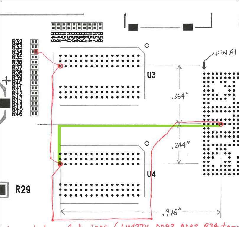
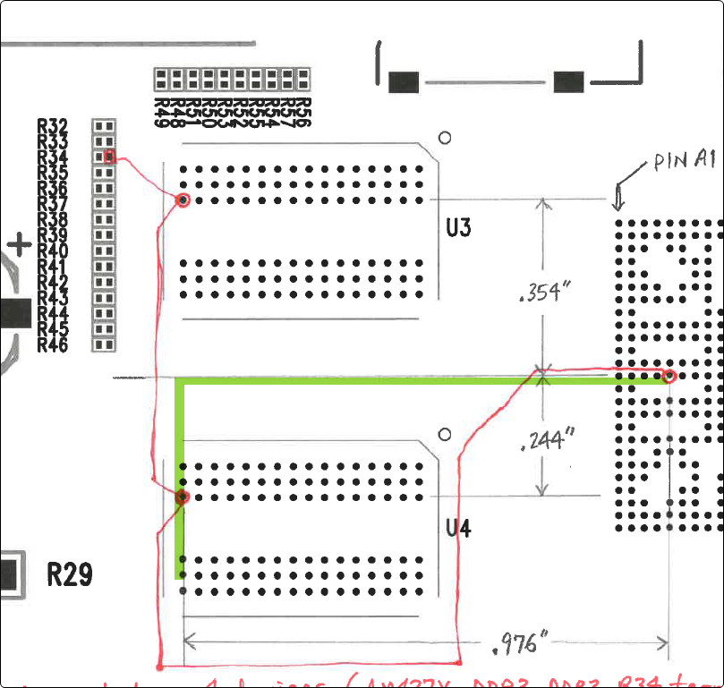
I have designed a custom board with a AM4378, and it has 2 (16 bit) DDR3 chips on the same side of the board. The size and shape of the board have forced me to locate the DDR3s in a way that doesn't quite match the recommendations in the datasheet (Figure 5-76), so I am having a difficult time determining Manhattan distance and max. trace lengths for address and clock nets. Below is some information about the layout.
FYI, we did build a first round of prototype boards, and the DDR3s do seem to be working fine, but I want to make sure we aren't just getting lucky, and would potentially have memory failures when we go to high volume production. Thanks in advance for your help.
Jan
Fundamentally, I think you may have an issue in the placement of U3 and U4. They look like they're placed as if you're going to do a balanced-T topology, but your actual routing is using a fly-by topology. I believe that's why your trace lengths are so long.
Best regards,
Brad
EDIT 4/26: Removed some of my original comments and markup...
Jan,
Sorry, I had my original drawing wrong. (James, thanks for jumping in!)
Here's a revised drawing. The manhattan distance is just a simple x-y distance:
According to your drawing this make the Manhattan distance for A13 equal to 976 mils + 244 mils = 1220 mils.
However, the data sheet is looking for the LONGEST Manhattan distance. So I believe that's going to correspond to A8:
Spec 15 in Table 58 (CK and ADDR_CTRL Routing Specification) of the data sheet is saying that all your trace lengths should be +/-50 mils of this longest Manhattan distance.
I hope this helps clarify things, and sorry for any confusion generated by my original post.
Best regards,
Brad
Brad,
Thanks for checking into this for me. I'll plan to make the necessary changes on the next spin.
Regards,
Jan