This thread has been locked.

If you have a related question, please click the "Ask a related question" button in the top right corner. The newly created question will be automatically linked to this question.

AM5728: AM5728 NOR flash for booting of AM5728

Part Number: AM5728
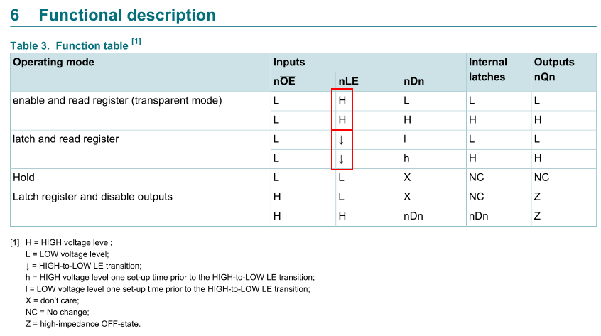
Other Parts Discussed in Thread: AM3359, SN74ALVCH16374

Hello

We are using parallel NOR flash for booting of AM5728 in MUXed MOde.

Can you please review the schematic for the same.

Schematic attached for the reference.AM5728_NOR FLASH.pdf

Regards

Akash Jain

  • Hi Akash,

    I quickly reviewed to the schematics you attached.

    Connecting DSP_NOR_DQ0 to A1 is correct - in AD mux mode the GPMC uses AD0 to carry the A1 address signal.
    I spot checked some other address signals, and they look correct for the AD mux mode.

    The GPMC ADVn_ALE is active low when accessing NOR Flash. It will be high at the beginning of the access cycle, low for a pulse then on the rising edge the memory/latch is expected to latch the address.
    Refer to AM5728 datasheet Figure 7-17. GPMC / Multiplexed NOR Flash - Asynchronous Read - Single Word Timing  

    On the 74ALVT16373, . When latch enable (nLE) input is HIGH, the nQn outputs follow the date (nDn) inputs. When latch
    enable is taken LOW, the nQn outputs are latched at the levels of the D inputs one setup time prior to the HIGH-to-LOW transition.

    I think you need an inverter before the nLE input so that on the rise edge of ADVn_ALE, the outputs are latched at the levels of the inputs. Then they are held at that state while ADVn_ALE is high.

    I recommend checking the impact on the signal timings with the latch in the loop when coming up with the GPMC config register values. These registers define the timing of the GPMC control signals, address latch, and data access times. The bootloader has default settings documented in Table 33-38. XIP Timing Parameters.

    What boot mode do you plan to use? See Table 33-9. Booting Devices Order and also Section 33.3.7 Memory Booting.
    Note that the Bootloader only uses CS0 to boot. You might need to use differnet configuration header (CH) to boot from this Flash + Latch. Refer to 33.3.8.2 Configuration Header.

    I recommend evaluating the NOR flash without bootloader first. Debug any issues communicating with the flash before attempting to bootload from it.

    Regards,
    Mark

  • Hello Mark

    Thanks for the quick review.

    Some questions based on your response:

    DSP_NOR_DQ0  is connected to A1 and AD0 is Muxed with DQ0 only on latch, so how to connect or is it correct only?

    For 74ALVT16373 they have internal inverter in the IC, can you please check once.

    We need to use NOR booting mode only, so for that is any change required in booting pins?

    Also Can you share some reference design or some eval boards having Nor Flash in AD mux mode?

    Regards

    Akash Jain

  • Hi Akash,

    I think the connection of GPMC_AD0 to A1 and DQ0 is correct. Sorry if I confused you.

    I checked the 74ALVT16373 datasheet again, and confirmed that the latch enable inputs are active HIGH, latching the inputs on the falling edge (and passing inputs to outputs when high). This wont work with the active low ADVn signal for NOR flashes. It needs to latch the input on the rising edge of ADVn.


    Refer to the AM3359 ICE board (www.ti.com/.../TMDSICE3359), where a latch (SN74ALVCH16374) is used to use GPMC in AD-mux mode with a NOR flash that does not support mux mode (requires all address lines to be driven). It connects the GPMC_ADVn signal to the CLK input. On the positive transition of the clock (CLK) input, the Q outputs of the flip-flop take on the logic levels at the data (D) inputs

    I'll have to loop in someone more expert for the bootloader questions. For now, refer the device TRM (SPRUHZ6K).
    33.3 Device Initialization by ROM Code
    33.3.5 Peripheral Booting
    33.3.6 Fast External Booting

    Regards,
    Mark

  • Hello Mark

    We have added the inverter IC , Request you have a look once again and confirm if all things are correct Now.

    Schematic Attached for your reference.

    Regards

    Akash JainAM5728_NOR.pdf

  • Hello Mark

    Have you got some time to look into the updated schematic

    We are waiting for your response.

    Regards

    Akash

  • Hi Akash,

    The inverter will logically allow this latch to assert the address bus to the memory for the entire write and read cycle.

    It introduces a propagation delay of 2.4ns (typical) from input to inverted output that needs to be factored into the timing analysis.

    The GPMC can certainly be configured to operate with this inverter, address latch, and NOR flash. But I cannot state that the bootloader will successfully boot without performing further timing analysis.

    Do you have an AM5728 board that you can probe the GPMC signals with during boot from GPMC?

    You could study the GPMC signal timings during GPMC boot, and then run the timing analysis to see if it will operate with the inverter, latch, and flash based on their timing requirements and switching characteristics.

    I'll loop in another engineer who might know more about the GPMC boot mode of the bootloader.

    Regards,
    Mark

  • Refer also to the TRM (SPRUHZ6).

    The GPMC-related sysboot pins are described in Table 33-6. And the GPMC config register bit fields are described in Table 33-38.

    It might be easier to probe the signals if you have an EVM available.

    Regards,
    Mark

  • Hello Mark

    Thanks for your quick response.

    Can you suggest some alternative Inverter, Latch, NOR by which we can directly meet our timing requirement of AM5728?

    Regards

    Akash

  • Hello Mark

    Any suggestions for above query, Awaiting feedback from our side.

    Regards

    Akash

  • Hi Akash,

    Sorry for the delay.

    I'm not confirming whether or not this NOR flash + latch and inverter combination will boot. I recommend you to calculate that the signal timings can meet the requirements using the data from the 3 datasheets and the GPMC configuration from the table in the TRM that I attached above.

    My concern is that ADVn is driven low on GPMC_FCLK cycle 1 then driven high on GPMC_FCLK cycle 2. The table does not specify the value for WRDATAONADMUXBUS (when the A/D mux data bus switches from address to data), but WEONTIME is set to 3 and usually for AD-mux devices, WEONTIME and WRDATAONADMUXBUS are equal. Could confirm this with an oscilloscope during that boot mode. Since there is the additional delay of the inverter before the latch, it erodes the hold time of the address on the data bus that is being latched by the delayed ADVn signal. If the AD bus transitions from address to data at GPMC_FCLK cycle 3, there will be 1 GPMC_FCLK cycle - 2.4ns (typical) left for the hold time.

    The AM572x datsheet Table 7-30. GPMC/NOR Flash Interface Switching Characteristics - Asynchronous Mode NO. FA28 further states that the Delay time from gpmc_wen valid to data bus valid is max of 2ns. It does not provide a min, assume 0ns.

    If the GPMC_FCLK is 266MHz (typical, but could confirm with scope capture in this boot mode), then the GPMC_FCLK period is 3.76ns. The hold time of the address at the latch might be 3.76 - 2.4ns = 1.36ns. I would definitely like to see more margin on the hold time.

    =-=-=-

    Have you done any searching to find NOR flash devices in any publicly available boards? Maybe a TI EVM, E2E question, or BeagleBoard daughter board.

    I didn't find any AM572x boards with an A/D-mux NOR flash. The only one I found was again that AM335x ICE board with a SN74ALVCH16374DGV latch. Since this latch does not require an inverter before it (latches on rise edge of clk that is fed by ADVn_ALE) it should not have the same hold time issue as the 74ALVT16373 in your design. Recommend you find a latch that doesn't require an external inverter.

    In the process of answering your question, I checked the sysboot signals in your design. The pull resistors and default jumper positions look good for a SD, XiP boot with GPMC Wait enabled, A/D mux device, with a 16-bit data bus. However, the text next to the pull-up/down resistors does not reflect the schematics - a bit misleading.

    Refer to AM335x_ICE_EVM: M29W160EB NOR - data through SN74ALVCH16374DGV (ALE is clock)
    http://www.ti.com/lit/df/tidr336/tidr336.zip

    Regards,
    Mark